- English
- French
- German
- Portuguese
- Spanish
- Russian
- Japanese
- Korean
- Arabic
- Greek
- German
- Turkish
- Italian
- Danish
- Romanian
- Indonesian
- Czech
- Afrikaans
- Swedish
- Polish
- Basque
- Catalan
- Esperanto
- Hindi
- Lao
- Albanian
- Amharic
- Armenian
- Azerbaijani
- Belarusian
- Bengali
- Bosnian
- Bulgarian
- Cebuano
- Chichewa
- Corsican
- Croatian
- Dutch
- Estonian
- Filipino
- Finnish
- Frisian
- Galician
- Georgian
- Gujarati
- Haitian
- Hausa
- Hawaiian
- Hebrew
- Hmong
- Hungarian
- Icelandic
- Igbo
- Javanese
- Kannada
- Kazakh
- Khmer
- Kurdish
- Kyrgyz
- Latin
- Latvian
- Lithuanian
- Luxembou..
- Macedonian
- Malagasy
- Malay
- Malayalam
- Maltese
- Maori
- Marathi
- Mongolian
- Burmese
- Nepali
- Norwegian
- Pashto
- Persian
- Punjabi
- Serbian
- Sesotho
- Sinhala
- Slovak
- Slovenian
- Somali
- Samoan
- Scots Gaelic
- Shona
- Sindhi
- Sundanese
- Swahili
- Tajik
- Tamil
- Telugu
- Thai
- Ukrainian
- Urdu
- Uzbek
- Vietnamese
- Welsh
- Xhosa
- Yiddish
- Yoruba
- Zulu
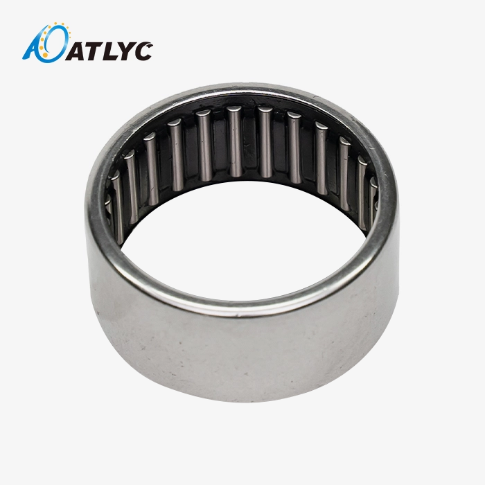
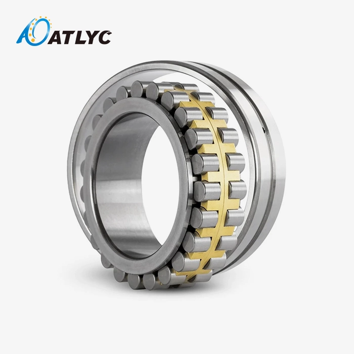
Can RE Cross Roller Bearings Handle Multi-Directional Loads?
Yes, RE Cross Roller Bearings are designed to handle loads that act in multiple directions simultaneously. These precision components can manage radial, axial, and moment forces within a single, compact unit, thanks to their split inner ring design, integrated outer ring, and cylindrical rollers positioned perpendicular to each other within V‑shaped raceways. This unique structural arrangement eliminates the need for multiple bearing configurations, simplifies application in challenging industrial environments, and provides high stiffness and rotational accuracy.
Understanding the Load Handling Capabilities of Cross Roller Bearings
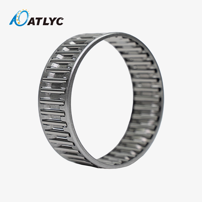
The unique layout of rollers in cross roller bearing technology is what makes it so strong. Standard ball bearings and single-row cylindrical roller bearings only handle loads that move in one direction. These special parts, on the other hand, use cylindrical rollers that are placed at right angles to each other. This straight-line arrangement makes alternate touch points on the track surfaces, which spreads forces over several load routes.
The Mechanical Principles Behind Multi-Directional Load Support
When your machine puts axial force on the bearing assembly, the load is supported by half of the wheels that are lying flat on the ground. When axial pressure happens at the same time, the vertically orientated wheels move to counteract it. Moment loads, which are the forces that cause robotic joints and rotary tables to tilt or flip, are controlled by both roller sets working together. Because of this way of distributing loads, a single bearing can be used instead of different sets of radial and thrust bearings.
The V-shaped form of the track makes this possible in a big way. The way each roller touches the track at an angle makes a shape that naturally fights movement in more than one direction. Spacers between neighbouring rollers keep them from touching directly, which lowers friction and keeps the exact distance between the rollers. This part of the design makes sure that the bearing can spin freely even when loads are mixed in a way that would cause less advanced bearings to become stuck.
Why This Design Excels in Demanding Industrial Environments
This type of bearing is always chosen by manufacturing engineers and buying specialists when room is limited, but performance needs are high. The structural strength of the entire outer ring is better than that of split-ring options. This is especially important when the outer ring moves around a stable inner assembly. This setup keeps the loading the same in all working situations, which stops the tiny movements that speed up wear in less rigid designs.
The raceway surfaces are machined to standards measured in micrometres. This makes sure that the load is evenly distributed across all rollers throughout the life of the bearing. The materials used, mostly Gcr15 and Gcr15SiMn bearing steels, are hard and stable in size, which is important for long-lasting performance under changing loads. These steels keep their structural features even in temperature ranges that are common in industrial machinery, such as clean rooms with climate control and areas near machines that get hot.

Comparative Analysis: Cross Roller Bearings vs. Other Bearing Types
Understanding how different bearing technologies compare helps engineering teams make informed component selections. Each bearing category offers specific advantages suited to particular application profiles, load characteristics, and operational requirements.
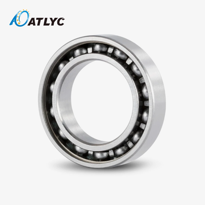
Performance Comparison with Ball Bearings
Standard ball bearings perform well in applications with moderate loads and high rotational speeds. Their point of contact with the raceways generates very low friction, enabling speeds that RE Cross Roller Bearings cannot match. However, this point contact significantly reduces load capacity. When heavy loads or high stiffness are required, ball bearings need larger dimensions or multiple bearing sets to achieve equivalent performance, whereas RE Cross Roller Bearings achieve superior load capacity and rigidity within a more compact envelope.
Cross roller bearing systems make direct contact between the rollers and the raceways, which spreads the power over a lot more surface area. Because of this shape, they can hold three to five times more weight than ball bearings of the same size. The trade-off is slightly higher friction coefficients and slower speeds because of them. But for robotic joints, machine tool spinning tables, and medical imaging equipment, the benefits of stiffness and load capacity are much more important than speed.
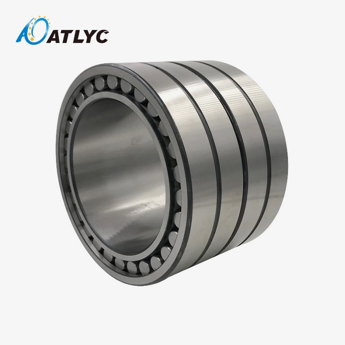
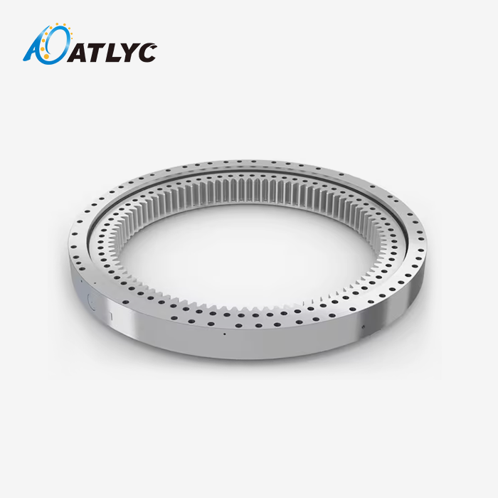
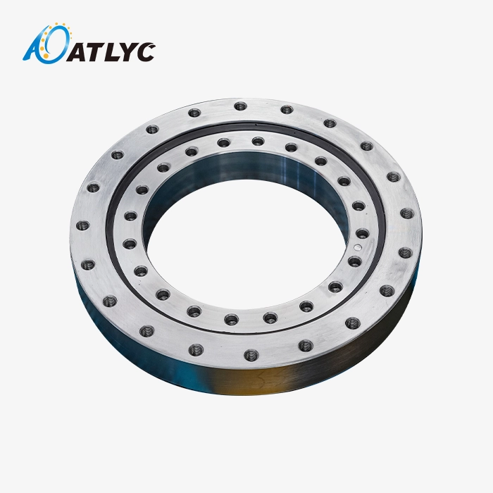
Distinguishing Features of Turntable and Slewing Bearings
Both turntable bearings and slewing rings can handle loads in more than one direction, but they are very different in size and purpose. Slewing bearings are usually used in machines with widths bigger than two meters, like building tools, wind turbines, and ship-to-shore cranes. When it comes to these huge structures, raw load capacity is more important than accuracy.
ATLYC makes bearings with inner diameters ranging from 20 mm to 1100 mm and outer diameters ranging from 70 mm to 1500 mm. This size range is for precise gear that needs to be able to hold a lot of weight and be accurate to the micrometre level. With widths ranging from 12mm to 110mm, they can be used in small equipment designs where every millimetre of room along the axis is important. The available precision grades—P6, P5, and P4—meet the high standards of equipment used to make semiconductors and measurement tools that need accurate settings over and over again.
Benchmark Analysis Against Global Bearing Brands
Procurement managers evaluating bearing suppliers naturally compare offerings from established brands such as NSK, SKF, Schaeffler, and KOYO against alternatives. These industry leaders set benchmarks for reliability, technical documentation, and global support networks. Over our 15 years of manufacturing experience at Luoyang Auto Bearing Co., Ltd., we've focused on matching and exceeding these standards while delivering the cost-performance ratio that mid-to-large OEMs require for competitive positioning.
Our ISO 9001 and IATF 16949 certifications demonstrate a commitment to quality management systems that parallel those of premium bearing manufacturers. The same heat treatment processes, grinding operations, and dimensional inspection protocols that global brands employ are standard practice across our six production workshops. What differentiates our value proposition is combining this manufacturing capability with the flexibility to accommodate custom specifications and the responsiveness that comes from direct manufacturer engagement rather than multi-layer distribution channels.
Quality metrics tell the story objectively. Defect rates, service life under controlled testing, and runout accuracy measurements from our production batches consistently meet international bearing standards. This performance reliability has established long-term supply relationships with automotive component manufacturers and industrial equipment OEMs across South Korea, the United States, Germany, Russia, Iran, and Turkey.
Key Advantages in Multi-Directional Load Applications
The practical benefits of cross roller bearing technology become evident when examining real-world installation and operational outcomes. Engineering teams specify these components because they solve multiple design challenges simultaneously while simplifying assembly processes.
High Load Capacity Within Compact Envelopes
Modern automation equipment demands ever-smaller footprints without sacrificing performance. A robotic joint that once required 200mm of axial space for dual bearing arrangements can often achieve superior stiffness using a single cross roller bearing occupying 50mm or less. This space efficiency cascades through the entire mechanism design, enabling lighter arm structures, reduced actuator sizes, and lower overall system inertia.
The integrated outer ring configuration eliminates the housing complexity associated with managing separate bearings. Your mechanical design team can mount the outer ring directly into the rotating structure using simple bolted connections or press-fits. The split inner ring facilitates roller installation during assembly—a practical advantage that reduces production line complexity compared to full-complement designs requiring specialized loading procedures.
Exceptional Rigidity and Precision Performance
Stiffness—the resistance to deflection under load—directly determines positioning accuracy in precision machinery. RE Cross Roller Bearings achieve rigidity values approaching those of solid metal joints while maintaining smooth rotation. The preload applied during manufacturing eliminates internal clearances, creating a mechanically stiff load path that minimizes deflection even when moment loads attempt to tilt the bearing races relative to each other. This characteristic is critical for applications such as machine tool rotary tables and robotic joints, where even micron‑level deviations can compromise part quality or assembly precision.
Measurement data from production testing validates this performance. Runout accuracy—the variation in radial and axial position during rotation—measures less than 5 micrometers in P5 grade bearings and below 2 micrometers in P4 grade components. This precision enables the repeatability that semiconductor handling robots require when placing silicon wafers into processing chambers, or the positioning accuracy that five-axis machining centers need for complex aerospace component manufacturing.
Durability and Maintenance Advantages in Industrial Settings
Component longevity directly impacts the total cost of ownership. Equipment downtime for bearing replacement involves not just parts cost but lost production time, labor expenses, and potential damage to adjacent components during disassembly. Cross roller bearings manufactured to proper specifications and operated within design parameters regularly achieve service lives measured in tens of thousands of operating hours.
The factors contributing to this durability start with material selection. Gcr15 and Gcr15SiMn steels undergo controlled heat treatment processes that develop uniform hardness throughout the raceway surfaces and roller bodies. This hardness—typically 58-62 HRC—resists the contact stresses generated during load cycling while maintaining sufficient core toughness to absorb shock loads without cracking.
Selecting the Right Cross Roller Bearing for Your Application: A Practical Guide
Bearing selection methodology begins with clearly defining the operating conditions and performance requirements your equipment imposes. This systematic approach prevents both over-specification—which inflates costs unnecessarily—and under-specification—which leads to premature failure and costly redesigns.
Defining Load Requirements and Operational Parameters
Start by quantifying the loads your bearing must support. Radial loads typically come from weight, tension in belts or cables, and process forces perpendicular to the axis of rotation. Axial loads result from thrust forces, pneumatic or hydraulic pressure, and components of angled force vectors. Moment loads arise whenever forces act at a distance from the bearing centerline—the longer the moment arm, the greater the tilting force the bearing experiences.
Dynamic loading conditions require additional consideration. If loads fluctuate during operation, the bearing selection must account for peak forces, not just average values. Impact loads from sudden starts or stops, or from processing operations like stamping or cutting, can generate force spikes several times higher than steady-state conditions. The bearing's dynamic load rating guides fatigue life under these cyclic loading patterns.
Matching Bearing Size and Accuracy Grade to Application Sectors
The dimensional envelope available in your equipment design constrains bearing size selection. Measure the shaft diameter, available housing bore, and axial space carefully. Cross roller bearing catalogs organize products by inner diameter, outer diameter, and width dimensions, allowing quick identification of candidates fitting your space constraints.
The sectors driving bearing demand have distinct priorities. Robotics applications emphasize compact size and weight reduction, accepting moderate accuracy grades (P5 or P6) where positioning precision depends more on encoder feedback than bearing runout. Machine tool rotary tables demand higher accuracy grades (P4 or P5) because workpiece positioning directly reflects bearing precision. Medical imaging equipment splits the difference—CT scanner gantries need smooth rotation to prevent image artifacts, but can accommodate P5 accuracy with proper balance optimization.
Procurement Considerations: Customization, Volume, and Supplier Reliability
Standard catalog RE Cross Roller Bearings meet most application needs, but custom modifications address specific challenges. Mounting hole patterns, sealing arrangements, and material variations represent common customization requests. At Luoyang Auto Bearing Co., Ltd., our 120-person team includes engineers experienced in translating application requirements into manufacturable bearing specifications. Custom bearing development for the RE series typically involves prototype production, testing, validation, and production process optimization before volume manufacturing begins.
Order volume affects both pricing and delivery schedules. Production lots ranging from tens to thousands of units allow economies of scale while maintaining flexibility for application-specific requirements. Our six workshop facilities provide capacity to support both prototype quantities for new equipment development and sustained production volumes for established product lines.s.
Maintenance Best Practices to Maximize Performance and Service Life
Preventive maintenance programs directly influence bearing longevity and equipment uptime. The relatively simple maintenance requirements of cross roller bearings contribute to their total cost advantage, but neglecting basic care accelerates wear and risks unexpected failures.
Routine Inspection Procedures
Visual inspection catches early warning signs before minor issues escalate. During scheduled maintenance intervals, examine the bearing installation for proper mounting—loose bolts or fitting rings indicate inadequate preload or clamping force. Check seal integrity if your bearing incorporates contact or non-contact seals; damaged seals allow contaminant ingress that rapidly degrades performance.
Listen for abnormal noise during operation. Properly functioning bearings produce a consistent low-frequency sound characteristic of rolling contact. Grinding, clicking, or periodic noise patterns suggest contamination, inadequate lubrication, or damage requiring investigation. Temperature monitoring provides another diagnostic indicator—bearings running substantially hotter than baseline temperatures may suffer from excessive preload, inadequate lubrication, or bearing distress.
Lubrication Standards and Practices
Proper lubrication separates bearing surfaces, reduces friction, removes heat, and protects against corrosion. Cross roller bearings typically use grease lubrication for simplicity and effectiveness across moderate speed ranges. Grease selection depends on operating temperature, speed, load, and environmental conditions.
General-purpose lithium-based greases suit many industrial applications, providing adequate performance from -20°C to +120°C. High-temperature applications—those regularly exceeding 100°C—require synthetic greases with polyurea or perfluoropolyether base stocks maintaining consistency and lubrication effectiveness above 150°C. Clean room environments demand greases formulated to minimize outgassing and particle generation.
Troubleshooting Common Issues and Preventive Strategies
Premature wear patterns provide diagnostic information about operating conditions. Localized wear on specific portions of the raceway indicates misalignment between the bearing and mating components. Proper installation procedures using precision measuring tools prevent misalignment during assembly. Confirm that mounting surfaces meet flatness and perpendicularity specifications—distorted housings or bent shafts impose bending loads that accelerate wear.
Contamination remains the leading cause of bearing failure across all types. Particles entering the bearing raceway create indentations that concentrate stresses, initiating fatigue cracks. Effective sealing systems represent the primary defense against contamination. For bearings without integral seals, housing designs should incorporate labyrinth seals, contact seals, or positive pressure barriers preventing ingress of dust, moisture, and process contaminants.

Conclusion
Cross roller bearing technology, including RE Cross Roller Bearings, delivers proven multi-directional load handling capability that simplifies equipment design while enhancing performance. The integrated outer ring and split inner ring configuration, combined with orthogonal roller arrangement, enables these precision components to simultaneously manage radial, axial, and moment forces within compact installation envelopes. This capability eliminates complex bearing arrangements, reduces weight, and improves rigidity compared to alternative solutions.
Manufacturing quality, material selection, and precision machining determine whether bearings meet the demanding requirements of robotics, machine tools, medical equipment, and semiconductor manufacturing. Adherence to ISO 9001 and IATF 16949 quality standards ensures consistency across production volumes. Proper selection methodology matching bearing specifications to application requirements, combined with preventive maintenance practices, maximizes service life and equipment reliability. As automation and precision manufacturing continue advancing, cross roller bearings remain essential components enabling the compact, high-performance designs that define modern industrial equipment.
FAQ
Are cross roller bearings suitable for high-speed robotic applications?
Cross roller bearing designs optimize load capacity and rigidity rather than maximum speed capability. Most robotic joints operate within speed ranges where these bearings perform reliably—typically below 500 RPM, depending on bearing size. The exceptional stiffness and multi-directional load handling capability make them ideal for robotic applications despite moderate speed ratings. For high-speed spindle applications exceeding 1000 RPM, angular contact ball bearings or cylindrical roller bearings may better suit requirements.
How do cross roller bearings compare to angular contact bearings for specific applications?
Angular contact bearings excel in applications requiring high axial load capacity in one direction at high speeds. Machine tool spindles represent their primary application domain. Cross roller bearing assemblies handle bidirectional axial loads, radial loads, and moment loads simultaneously, making them preferable for rotary tables, robotic joints, and positioning systems where loads come from multiple directions. The selection depends on whether your application involves primarily unidirectional thrust or combined multi-directional loading.
What are typical lead times for custom bearing orders?
Standard catalog bearings typically ship within two to four weeks, depending on quantity and current production schedules. Custom bearing specifications require engineering review, prototype production, and testing before volume manufacturing begins. This process generally extends lead times to eight to twelve weeks for initial orders. Subsequent production runs of approved custom designs follow shorter schedules similar to standard products. At ATLYC, we work closely with customers to establish realistic schedules accommodating both engineering requirements and production needs.
Partner with ATLYC for Reliable Cross Roller Bearing Solutions
ATLYC brings 15 years of bearing manufacturing expertise to support your precision motion control requirements. Our comprehensive cross roller bearing catalog, including RE Cross Roller Bearings, spans inner diameters from 20mm to 1100mm with accuracy grades from P6 to P4, manufactured under ISO 9001 and IATF 16949 certified quality systems. The integrated outer ring designs we produce deliver the multi-directional load capacity, rigidity, and rotational precision that robotic systems, machine tools, and medical equipment demand.
Our technical team understands the procurement challenges mid-to-large OEMs face—stable supply chains, consistent quality, competitive pricing, and responsive engineering support. We manufacture cross roller bearings using Gcr15 and Gcr15SiMn materials with documented performance meeting international standards, backed by rigorous testing protocols ensuring low defect rates. Whether you need standard catalog components or custom specifications for specialized applications, our production capacity and engineering capabilities support both prototype development and volume manufacturing.
Contact our bearing specialists at auto@lyautobearing.com to discuss your application requirements. We'll provide technical consultation matching bearing specifications to your operating conditions, competitive quotes reflecting our position as a direct manufacturer and supplier, and delivery schedules supporting your production timelines. Request detailed specifications, application engineering support, or sample quantities to validate performance in your equipment before committing to volume orders.
References
1. Harris, T. A. & Kotzalas, M. N. (2006). Rolling Bearing Analysis: Essential Concepts of Bearing Technology (5th ed.). CRC Press.
2. Hamrock, B. J., Schmid, S. R., & Jacobson, B. O. (2004). Fundamentals of Fluid Film Lubrication (2nd ed.). Marcel Dekker.
3. ISO 199:2014. Rolling Bearings — Thrust Bearings — Geometrical Product Specifications (GPS) and Tolerance Values. International Organization for Standardization.
4. Weck, M. & Brecher, C. (2006). Machine Tools Production Systems 2: Design and Calculation. Springer-Verlag Berlin Heidelberg.
5. Budynas, R. G. & Nisbett, J. K. (2015). Shigley's Mechanical Engineering Design (10th ed.). McGraw-Hill Education.
6. Eschmann, P., Hasbargen, L. & Weigand, K. (1985). Ball and Roller Bearings: Theory, Design and Application (2nd ed.). John Wiley & Sons.
Learn about our latest products and discounts through SMS or email