- English
- French
- German
- Portuguese
- Spanish
- Russian
- Japanese
- Korean
- Arabic
- Greek
- German
- Turkish
- Italian
- Danish
- Romanian
- Indonesian
- Czech
- Afrikaans
- Swedish
- Polish
- Basque
- Catalan
- Esperanto
- Hindi
- Lao
- Albanian
- Amharic
- Armenian
- Azerbaijani
- Belarusian
- Bengali
- Bosnian
- Bulgarian
- Cebuano
- Chichewa
- Corsican
- Croatian
- Dutch
- Estonian
- Filipino
- Finnish
- Frisian
- Galician
- Georgian
- Gujarati
- Haitian
- Hausa
- Hawaiian
- Hebrew
- Hmong
- Hungarian
- Icelandic
- Igbo
- Javanese
- Kannada
- Kazakh
- Khmer
- Kurdish
- Kyrgyz
- Latin
- Latvian
- Lithuanian
- Luxembou..
- Macedonian
- Malagasy
- Malay
- Malayalam
- Maltese
- Maori
- Marathi
- Mongolian
- Burmese
- Nepali
- Norwegian
- Pashto
- Persian
- Punjabi
- Serbian
- Sesotho
- Sinhala
- Slovak
- Slovenian
- Somali
- Samoan
- Scots Gaelic
- Shona
- Sindhi
- Sundanese
- Swahili
- Tajik
- Tamil
- Telugu
- Thai
- Ukrainian
- Urdu
- Uzbek
- Vietnamese
- Welsh
- Xhosa
- Yiddish
- Yoruba
- Zulu
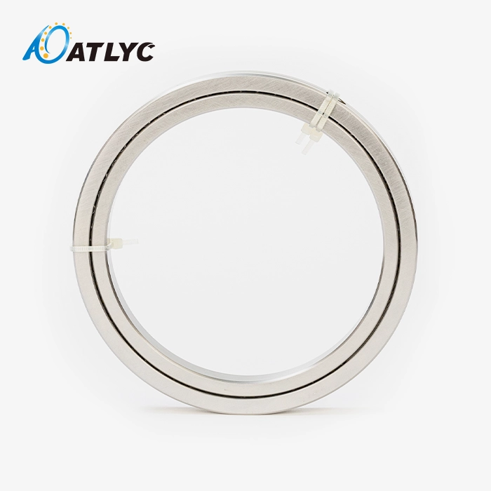
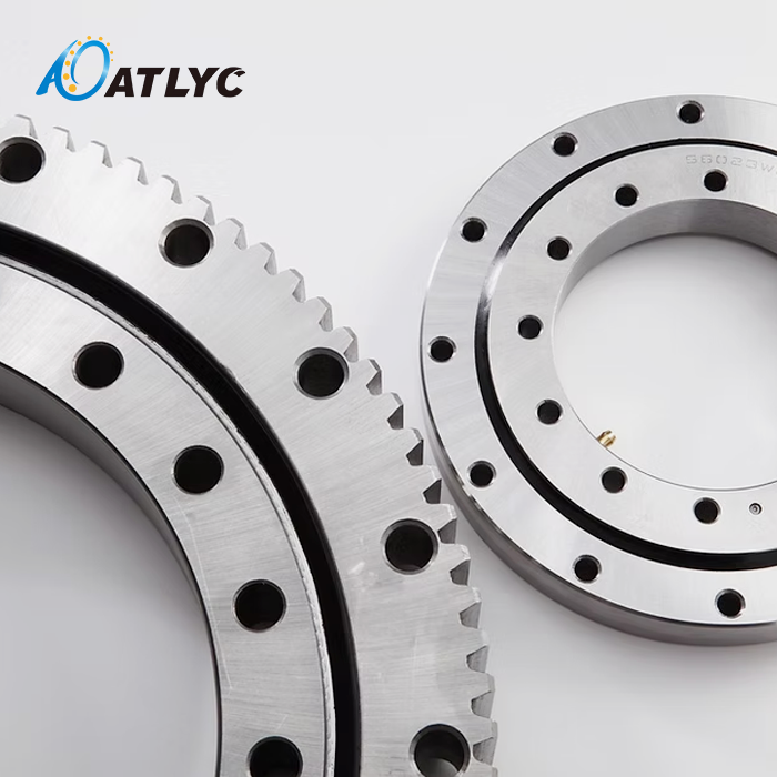
How to Install Crossed Roller Bearing RB Series?
When installing the Crossed Roller Bearing RB Series, it's important to pay close attention to how the mounting area is prepared, how it's aligned, how much pressure is applied, and how it's oiled. To keep the orthogonal roller arrangement, care must be taken when handling the inner ring that is merged and the outer ring that can be separated and has a plug design. To get the best rigidity and multidirectional load capacity from these precision bearings in robotic joints, machining centers, and automation equipment, you need to use calibrated torque tools, keep the work area clean, and follow the manufacturer's instructions.

Introduction
The RB Series crossed roller bearings are a big step forward in controlling motion precisely for tough industrial uses. These bearings are designed to work in places with limited room and big loads. They provide the strength and accuracy that current robotic systems need. This bearing technology is used in many fields, from robots and aircraft to making medical devices. It keeps positioning accuracy within microns while handling complex load combinations.
The RB Series is different from other bearings because it can handle radial, axial, and moment loads all at the same time in a single, small unit. This feature gets rid of the need for paired angled contact ball bearings, which makes the structure simpler and lighter overall. The crossed cylinder roller setup at 90-degree angles makes the structure very stiff, so it doesn't bend much when it's under stress from work.
In B2B buying situations, the difference between great success and early failure is the proper installation. Manufacturers lose thousands of dollars every hour when their equipment breaks down, so accurate installation is a direct way for them to make money. That's why this complete guide shows you tried-and-true ways to install industrial robots, precision rotary tables, and machining centers, based on years of experience in the field. We'll talk about the technical details of the RB Series, how to prepare your bearings so they don't fail because of contamination, and the step-by-step steps you need to take to make sure your bearings last the 20,000+ hours of constant duty that they are rated for.
Understanding Crossed Roller Bearing RB Series Before Installation
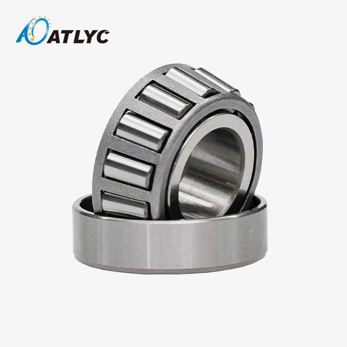
To do a good job installing something, you need to know everything there is to know about the RB Series bearing design. This bearing system uses circular wheels in line contact with V-groove raceways instead of point contact, like most ball bearings do. This basic change in design makes the structure much more rigid and able to hold more weight while keeping the same envelope size.
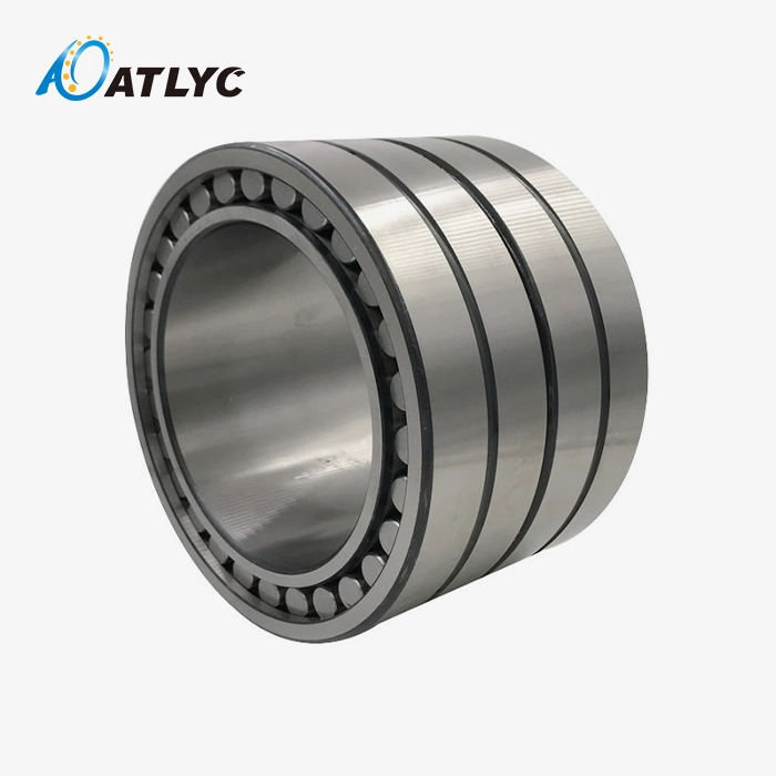
Structural Design and Load Distribution Principles
The RB Series has a combined inner ring design that makes it very stable in terms of size while it's rotating. This one-piece inner ring doesn't have any joint surfaces like split-ring designs do. This stops the tiny deflections that add up to positioning mistakes in precision applications. The outer ring can be broken down into two parts that are held together by a plug-based system. This makes it easy to attach to shafts while still keeping the structural integrity needed for moment load resistance.
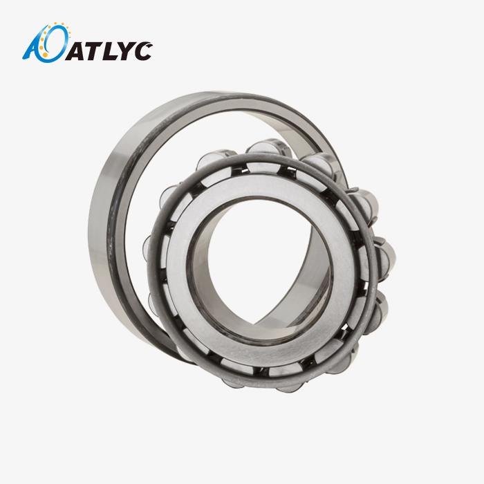
There is a series of cylindrical rollers that are arranged at right angles to both the inner and outer ring raceways. Precision spacing spacers put each roller in the right place so that they don't move or rub against each other while they're running. This setup is orthogonal, so each roller set can handle different types of loads. For example, one set handles circular forces, and the perpendicular set handles axial loads. The V-groove raceway design makes the best contact angles that spread moment loads evenly across all wheel parts at the same time.
Technical Specifications and Material Properties
The sizes range from small 20mm units with an inner circle that can be used for medical tools to huge 1100mm units that power heavy-duty spinning tables. The outside lengths range from 70 mm to 1500 mm, and the widths range from 12 mm to 110 mm. This wide range of sizes lets engineers choose the exact bearing that fits the space limitations and load needs of their application.
GCr15 bearing steel and GCr15SiMn alloy are the main materials chosen. Both of these are heat-treated to an HRC of 58 to 64. These steels with chromium in them have the underlying strength to handle the high pressures at the places where the rollers and raceways meet. The silicon-manganese version is better at hardening larger cross-sections, so it can be used for through-hardening in widths bigger than 50 mm. Specifications for surface finish keep Ra values below 0.2 micrometres on all load-bearing surfaces. This lowers friction coefficients and increases wear life.
Performance Characteristics That Drive Application Selection
When you examine the performance range of the Crossed Roller Bearing RB Series, you can see why positioning accuracy is so critical. As standard, these bearings achieve P5 and P4 accuracy grades, with P2 ultra-precision variants available for semiconductor manufacturing equipment. Runout tolerances are maintained within 5 microns for P5 grade and 2.5 microns for P4, enabling positioning repeatability that satisfies the most demanding automation requirements.
The ability to hold loads in more than one way is especially useful in robotic joint uses. A normal 100mm size RB Series bearing can handle a radial load of 45kN, an axial load of 35kN, and a moment load of 4kN-m all at the same time. In most designs, these loads would need three different types of bearings. When properly oiled, friction rates are between 0.002 and 0.003, which is a lot lower than the range of 0.001-0.0015 for ball bearings. This lower friction directly leads to less power being needed by the actuator and less heat being generated during constant operation.
Application flexibility covers a wide range of business areas. Manufacturers of industrial robots put these bearings at every point of joint where precise motion control decides how accurately the end-effector is placed. The moment load capacity of the bearing is what keeps the workpiece aligned during multi-axis cutting processes on the machining center's rotating tables. The smooth, low-torque spinning for CT scanner gantries is used in medical imaging tools. Semiconductor production tools define the ultra-precision grades for chip handling stages where output rates depend on placement to within a few microns.
Preparing for Installation: Essential Tools and Pre-Installation Checks
Successful installation outcomes depend heavily on preparation quality. Rushing through preliminary steps creates the conditions for installation errors that manifest as premature bearing failure months later. We've documented installation protocols refined through supporting hundreds of OEM production lines, and these preparation guidelines consistently prevent the most common failure modes.
Required Tools and Measurement Equipment
Precision installation demands precision tools. Your toolkit must include calibrated torque wrenches spanning the range appropriate for your bearing size—typically 5-50 N-m for smaller units and 50-500 N-m for industrial-scale bearings. Digital torque tools with data logging capability provide documentation for quality management systems compliant with ISO 9001 and IATF 16949 standards. Dial indicators with magnetic bases enable runout verification during installation, confirming concentricity within specification before final tightening.
Micrometers and bore gauges verify mounting surface dimensions against bearing tolerance requirements. Housing bore diameters must hold H7 tolerance for proper bearing fit, while shaft diameters require h6 precision. Cleanliness supplies prove equally critical—lint-free cloths, precision cleaning solvents approved for bearing applications, and filtered compressed air systems prevent contamination introduction. Proper lubricants selected according to operating temperature and speed parameters ensure adequate film formation from initial startup.
Pre-Installation Inspection Protocols
Visual inspection begins your quality verification sequence. Examine the bearing exterior for shipping damage, checking that protective packaging remained intact until installation. Rotate the bearing slowly by hand, feeling for smooth, consistent resistance throughout the rotation. Any catching, roughness, or variation indicates potential damage requiring manufacturer consultation before proceeding.
Measure critical dimensions to confirm specification compliance. Verify inner diameter, outer diameter, and width against the dimensional drawing tolerances. Check the outer ring plug retention—it should sit flush without gaps or protrusions. Inspect mounting surfaces on both housing and shaft, looking for burrs, nicks, or corrosion that could create stress concentrations. Surface finish measurements should confirm Ra values below 1.6 micrometers on all bearing contact surfaces.
Cleanliness and Contamination Prevention
Contamination accounts for approximately 40% of premature failures of Crossed Roller Bearing RB Series, according to industry failure analysis data. Establishing a clean installation environment significantly extends bearing service life. Ideally, install in a controlled environment with filtered air to ISO Class 7 cleanliness or better. When field installation proves necessary, create a localized clean zone using portable enclosures and HEPA filtration.
Clean all components with bearing-grade solvents immediately before assembly. Remove the bearing from its protective packaging only when mounting surfaces are prepared and cleaned. Handle bearings with clean cotton or nitrile gloves—skin oils contain corrosive acids that initiate rust formation. Store bearings in sealed containers with desiccant if installation delays occur, preventing atmospheric moisture contamination of the precision-ground surfaces.
Step-by-Step Installation Process for RB Series Crossed Roller Bearings
The installation sequence follows a logical progression that builds accuracy at each stage. Deviations from this procedure risk misalignment accumulation that compromises bearing performance. We've structured these steps based on field-tested protocols used in automotive assembly lines and precision machine tool manufacturing.
Surface Preparation and Alignment Verification
Begin by thoroughly cleaning the shaft and housing bore with approved solvents, removing all traces of protective coatings, machining residues, and contamination. Dry surfaces completely using filtered compressed air, ensuring no solvent residue remains that could compromise lubrication effectiveness. Apply a thin film of assembly lubricant to the shaft mounting surface—this prevents galling during bearing installation while facilitating proper positioning.
Mount the housing in a stable, level position using precision fixturing. Verify the mounting surface perpendicularity using a dial indicator swept across the bore face. Perpendicularity errors exceeding 0.02mm per 100mm diameter create axial preload variations that accelerate wear. Check bore cylindricity and concentricity relative to datum features—out-of-round conditions generate uneven stress distributions across the bearing circumference.
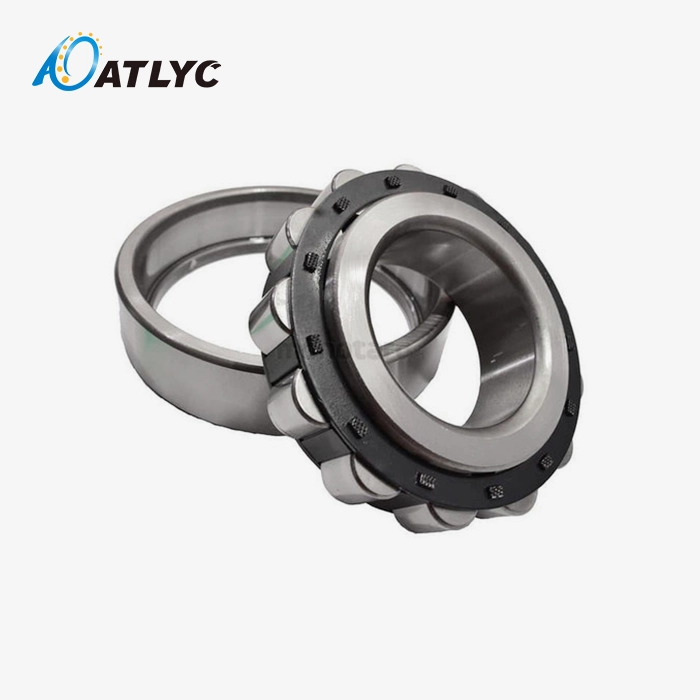
Bearing Orientation and Installation Sequence
The RB Series bearing orientation critically affects load distribution. Position the bearing so that the outer ring plug faces the direction allowing the easiest access for preload adjustment after installation. The integrated inner ring simplifies orientation—slide it onto the shaft using steady, even pressure. Never strike the bearing with hammers or hard tools; impact loads damage the precision-ground raceways and can dislodge rollers from their retainers.
For interference fits, heating provides the safest installation method. Use induction heaters or bearing heater plates to raise bearing temperature 80-100°C above ambient. This thermal expansion creates sufficient clearance for slip-fit installation without excessive force. Monitor temperature with calibrated instruments—exceeding 120°C risks tempering the bearing steel and degrading hardness. Install the heated bearing promptly while maintaining alignment, allowing natural cooling to establish the interference fit.
Press-fit installations require specialized tooling that applies force to the correct bearing ring. The RB Series integrated inner ring means installation force must transfer through the inner ring face, never through rollers or the outer ring. Custom-designed installation sleeves distribute force evenly around the circumference, preventing ring deformation. Apply force gradually while monitoring alignment with dial indicators positioned at 90-degree intervals around the bearing.
Preload Application and Torque Control
Proper preload establishes the zero-clearance condition necessary for precision positioning. The RB Series achieves preload through controlled axial clamping of the outer ring assembly. The plug-based design allows straightforward adjustment—tighten mounting bolts in a star pattern, progressing incrementally to distribute clamping force uniformly. Torque specifications vary with bearing size; consult manufacturer documentation for values specific to your model.
Measure preload indirectly through starting torque verification. Rotate the bearing while measuring torque with a calibrated instrument. Acceptable starting torque ranges typically span 1.5-3.0 times the calculated running torque based on bearing size and lubrication. Insufficient preload allows internal clearances that degrade positioning accuracy, while excessive preload accelerates fatigue wear and increases friction losses.
Lubrication Application Methods
Lubrication quality directly impacts bearing service life. Select grease formulations designed for precision bearings operating in your temperature and speed ranges. Lithium complex greases with ISO VG 68-100 base oils suit most industrial applications, while synthetic PAO or ester-based greases serve extreme temperature environments. Apply grease to fill 30-40% of the bearing's free internal volume—overfilling creates churning resistance that generates excessive heat.
During installation of Crossed Roller Bearing RB Series, distribute lubricant evenly across all roller and raceway surfaces. Rotate the bearing several complete revolutions after grease application, working lubricant into the contact zones. For oil lubrication systems, establish minimum flow rates that maintain adequate film thickness without excessive churning losses. Oil viscosity selection balances film formation requirements against friction minimization—typically ISO VG 46–68 for speeds below 500 RPM and VG 22–32 for higher speeds.
Final Inspection and Operational Verification
Complete installation with systematic verification checks. Measure axial and radial runout at multiple circumferential positions, confirming values remain within bearing accuracy grade specifications. Rotate the bearing through multiple revolutions, sensing for smooth, consistent torque. Listen carefully for any unusual sounds—clicking, grinding, or periodic noise indicates potential assembly errors requiring immediate investigation.
Check mounting bolt torque values after initial rotation, retightening any fasteners that relaxed during seating. Verify that locking mechanisms engage properly, preventing preload loss during service. Document all installation measurements and torque values for quality records and future maintenance reference. This documentation proves invaluable for troubleshooting should operational issues emerge and establishes baseline data for condition monitoring programs.
Common Installation Challenges and How to Avoid Them
Years of supporting production installations across automotive and industrial automation sectors have revealed recurring challenges. Understanding these failure modes and their prevention strategies protects your equipment investment and maintains production uptime.
Misalignment and Its Cascading Effects
Angular misalignment between the shaft and housing bores creates uneven load distribution across the roller elements of the Crossed Roller Bearing RB Series. Even 0.1-degree misalignment concentrates loads on a narrow band of rollers, accelerating surface fatigue and reducing bearing life by 50% or more. This problem manifests gradually—initial operation appears normal, but wear accelerates exponentially as surface damage progresses.
Contamination Introduction During Assembly
Particulate contamination as small as 10 microns initiates surface damage through indentation and abrasive wear. Moisture contamination proves equally destructive, creating corrosion pits that serve as fatigue crack initiation sites. Installation environments in typical machine shops contain both contaminants in concentrations that guarantee premature bearing failure without proper protection.
Incorrect Preload Settings and Adjustment
Insufficient preload allows internal clearances that create positioning errors and roller skewing. Rollers slide rather than roll, generating friction and heat that degrade lubrication effectiveness. Conversely, excessive preload overloads contact surfaces, exceeding material fatigue limits and dramatically shortening bearing life. Both conditions prove difficult to detect during initial commissioning but reveal themselves through premature failure.
Real-World Success: Automotive Assembly Line Implementation
An automotive manufacturer approached us, facing chronic bearing failures on their robotic welding line. Analysis revealed that installation procedures allowed contamination introduction and failed to verify alignment adequately. We developed a structured installation protocol incorporating clean assembly practices, precision alignment verification, and documented torque procedures. Implementation reduced bearing failures by 85% over the subsequent 18-month period, eliminating costly production disruptions and validating the importance of disciplined installation practices in high-volume manufacturing environments.
Maintenance Tips Post-Installation to Maximize Bearing Life
Regular inspection schedules should commence immediately after commissioning. Monitor bearing temperature during initial operation—readings should stabilize below 70°C for properly installed bearings operating under normal loads. Temperature spikes indicate potential problems such as inadequate lubrication, excessive preload, or misalignment issues requiring investigation. Vibration analysis provides early warning of developing problems, with spectrum analysis identifying specific bearing defects through characteristic frequency patterns.

Conclusion
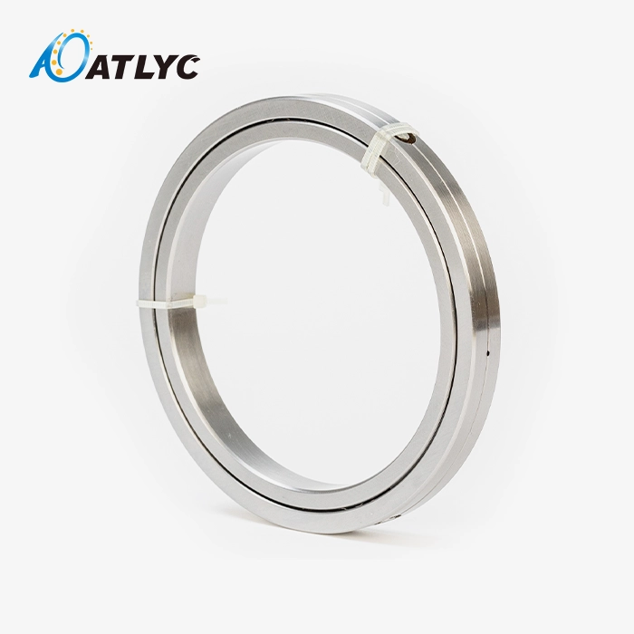
Installing the Crossed Roller Bearing RB Series demands precision, cleanliness, and strict adherence to proven procedures. The integrated inner ring and separable outer ring design offers exceptional load capacity and rigidity, but only when installation protocols preserve the bearing's precision characteristics. Proper surface preparation, controlled preload application, and contamination prevention transform this advanced bearing technology into decades of reliable service across robotics, machining centers, and automation equipment. The investment in specialized tools, clean assembly environments, and trained personnel pays dividends through extended bearing life, minimized downtime, and consistent positioning accuracy that maintains product quality.
FAQ
How long does Crossed Roller Bearing RB Series installation typically take?
Installation duration varies with bearing size and application complexity. Small-diameter bearings (20-100mm ID) typically require 2-4 hours, including preparation, while large industrial units (500mm+ ID) may need 8-12 hours. Proper preparation accounts for roughly 40% of total time—rushing this phase creates problems that extend troubleshooting time significantly.
What specialized tools are required for RB Series installation?
Essential tools include calibrated torque wrenches matching your bearing's fastener specifications, dial indicators with magnetic bases for runout verification, micrometers or bore gauges for dimensional checking, and precision cleaning supplies. Larger bearings benefit from induction heaters for thermal installation methods and hydraulic presses with custom sleeves for force-controlled mounting.
How does RB Series installation differ from slewing ring bearing installation?
The RB Series integrated inner ring and separable outer ring with plug creates distinct installation requirements compared to slewing rings. RB bearings mount more like conventional bearings with shaft and housing fits, while slewing rings bolt directly to mating structures. The RB Series requires precise preload adjustment through axial clamping, whereas slewing rings typically operate with controlled clearance. Both demand meticulous alignment, but the RB Series achieves tighter accuracy grades suitable for precision positioning applications.
Partner with a Certified Crossed Roller Bearing RB Series Manufacturer
ATLYC brings 15 years of precision bearing manufacturing expertise directly to your production line. As an ISO 9001 and IATF 16949 certified manufacturer, we've expanded from a single workshop in 2010 to six specialized production facilities serving automotive OEMs and industrial equipment manufacturers worldwide. Our RB Series crossed roller bearings deliver the exceptional rigidity and multi-directional load capacity your automation equipment demands, backed by comprehensive technical support throughout specification, installation, and lifecycle management.
Contact our engineering team at auto@lyautobearing.com to discuss your application requirements. We provide detailed installation guidance, custom preload specifications, and ongoing technical consultation that ensures optimal bearing performance. Our production capacity supports both prototype quantities and high-volume manufacturing runs, with lead times tailored to your project schedules. ATLYC serves as your reliable Crossed Roller Bearing RB Series supplier, combining precision manufacturing standards with responsive customer service across North America, Europe, and Asia.
References
1. Harris, Tedric A. and Kotzalas, Michael N. "Advanced Concepts of Bearing Technology: Rolling Bearing Analysis, Fifth Edition." CRC Press, 2006.
2. Eschmann, Paul, Hasbargen, Ludwig, and Weigand, Karl. "Ball and Roller Bearings: Theory, Design and Application, Third Edition." John Wiley & Sons, 1985.
3. Hamrock, Bernard J. and Dowson, Duncan. "Ball Bearing Lubrication: The Elastohydrodynamics of Elliptical Contacts." John Wiley & Sons, 1981.
4. ISO 199:2014. "Rolling bearings — Thrust bearings — Geometrical product specifications (GPS) and tolerance values." International Organization for Standardization, 2014.
5. Tallian, Tibor E. "Failure Atlas for Hertz Contact Machine Elements, Second Edition." American Society of Mechanical Engineers Press, 1999.
6. Witte, Donald C. "Operating Practices and Procedures for Extending Rolling Element Bearing Life in Industrial Applications." Society of Tribologists and Lubrication Engineers Special Publication, 1991.
Learn about our latest products and discounts through SMS or email