- English
- French
- German
- Portuguese
- Spanish
- Russian
- Japanese
- Korean
- Arabic
- Greek
- German
- Turkish
- Italian
- Danish
- Romanian
- Indonesian
- Czech
- Afrikaans
- Swedish
- Polish
- Basque
- Catalan
- Esperanto
- Hindi
- Lao
- Albanian
- Amharic
- Armenian
- Azerbaijani
- Belarusian
- Bengali
- Bosnian
- Bulgarian
- Cebuano
- Chichewa
- Corsican
- Croatian
- Dutch
- Estonian
- Filipino
- Finnish
- Frisian
- Galician
- Georgian
- Gujarati
- Haitian
- Hausa
- Hawaiian
- Hebrew
- Hmong
- Hungarian
- Icelandic
- Igbo
- Javanese
- Kannada
- Kazakh
- Khmer
- Kurdish
- Kyrgyz
- Latin
- Latvian
- Lithuanian
- Luxembou..
- Macedonian
- Malagasy
- Malay
- Malayalam
- Maltese
- Maori
- Marathi
- Mongolian
- Burmese
- Nepali
- Norwegian
- Pashto
- Persian
- Punjabi
- Serbian
- Sesotho
- Sinhala
- Slovak
- Slovenian
- Somali
- Samoan
- Scots Gaelic
- Shona
- Sindhi
- Sundanese
- Swahili
- Tajik
- Tamil
- Telugu
- Thai
- Ukrainian
- Urdu
- Uzbek
- Vietnamese
- Welsh
- Xhosa
- Yiddish
- Yoruba
- Zulu
How to Align the Cross roller bearing RE series Inner Ring Properly?
Achieving precise inner ring orientation in Cross roller bearing RE series setups is essential to unlocking maximum performance in high-precision machinery. The split inner ring design of these bearings requires careful attention during assembly—specifically ensuring concentricity, proper seating against housing shoulders, and even torque distribution across fastening points. Misalignment by even micrometers affects load distribution across the orthogonally arranged cylinder wheels, leading to earlier wear patterns and sound problems. When you learn the alignment fundamentals specific to RE series setups with their combined outer rings and separated inner components, you protect your equipment investment while improving operating accuracy across demanding applications.
Understanding the Cross Roller Bearing RE Series Inner Ring Alignment
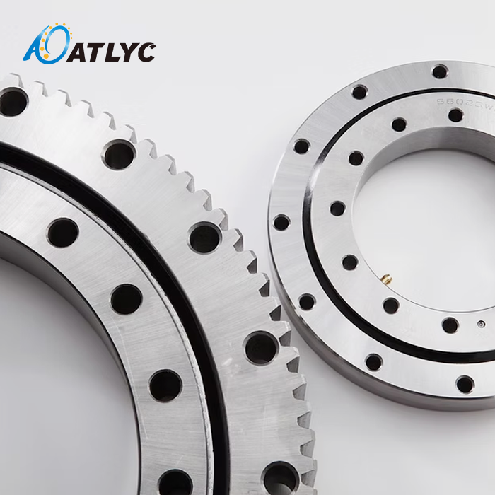
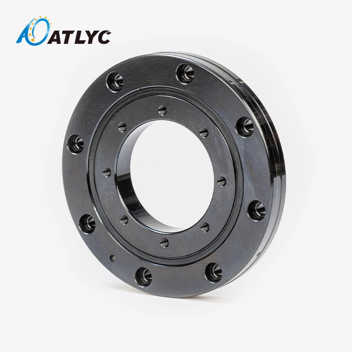
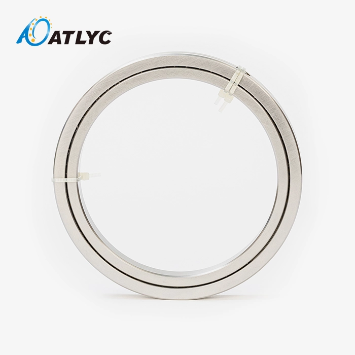
The design complexity of RE series crossed roller bearings sets them apart in precision motion control applications. Featuring an integral outer ring paired with a two-piece inner ring assembly, these bearings accommodate radial forces, axial loads, and moment capacities simultaneously within a remarkably compact footprint. The inner diameter range runs from 20mm to 1100mm, with outer diameters reaching 1500mm and widths stretching to 110mm, offering scalable options for diverse business needs.
Structural Design and Material Composition
Manufacturing these bearings from Gcr15 and Gcr15SiMn alloy steels ensures exceptional dimensional stability under varying thermal conditions. The hardened raceways maintain precision tolerances across accuracy grades from standard P6 to ultra-precise P2 classifications. This material selection directly impacts alignment retention, as thermal expansion factors affect how mounting gaps behave during working temperature changes.
The split inner ring configuration serves dual purposes—simplifying installation procedures while enabling maintenance access without complete bearing removal. Each half-ring maintains independent dimensional integrity, yet both must achieve perfect concentricity with the shaft diameter when assembled. The V-groove raceways cut into both rings provide contact surfaces for the crossed cylinder rollers positioned at 90-degree angles.
Why Precise Alignment Matters
When the rollers are properly aligned, the load paths stay the same at all contact points. When the inner ring halves are centred around the shaft and have the same amount of radial clearance, forces are spread evenly through the crossed roller matrix. This even distribution of load stops stress from building up in one area, which speeds up surface wear.
Misalignment leads to several operational problems. Differences in angles between the two halves of the inner ring make the loading conditions uneven, which means that some rollers have to carry loads that aren't right for them. When there is a mismatch, there is more friction, higher working temperatures, and noise. Over time, the uneven stress patterns eat away at the precision-ground raceways, making them less accurate for spinning and finally breaking them in a big way.
Manufacturers of robotic joints, machine center spinning tables, and precision medical devices rely on these Cross roller bearing RE series bearings to work consistently. Alignment is directly related to how accurate and consistent the positioning can be. These are important factors in automated manufacturing, where tolerance stack-ups determine the quality of the product.
Common Challenges and Causes of Misalignment in the RE Series Inner Ring
When installing crossed roller bearing assemblies, installation teams often run into problems that they can expect. By understanding these problems, you can take strategic steps to protect the health of the bearing.
Dimensional Deviations in Mounting Surfaces
Shaft shoulder perpendicularity is the most important thing to think about. The inner ring can't seat evenly if the shoulder face isn't perfectly straight in relation to the centerline of the shaft. An angle mismatch happens when one side touches the shoulder, and the other edge tilts away. Even differences of 0.01 mm can make alignment bad in high-precision situations.
Surface finish flaws on shaft journals or housing bores cause the same problems. Roughness peaks don't make continuous circumferential support; instead, they make localised contact points. When mounting torque is applied, the inner ring moulds to these flaws, locking in alignment mistakes.
Tolerance Stack-Up Effects
Dimensional changes are amplified in assembly processes with multiple parts. Individual part errors, such as shaft diameter, keyway depth, spacer ring thickness, and bolt measurements, add up to make the end bearing position unclear. These stack-ups are not within the allowed alignment limits because they were not carefully analysed for tolerances during the planning phase.
These problems are made worse by temperature differences during installation. When room-temperature bearings are put on shafts that have just been machined, thermal expansion mismatches happen. As temperatures level off, the parts move, which could change how they are aligned.
Inconsistent Fastening Procedures
Patterns of applying torque have a big effect on the final alignment. Randomly tightening mounting nuts causes crushing forces that aren't even around the edge. This uneven pressure distribution pulls the inner ring halves away from being concentrically balanced, causing uneven conditions that last the whole process.
Procedure errors are caused by operators not having enough training. Assembling skills vary between technicians because there aren't any standard instructions that spell out torque values, tightening sequences, and verification steps. Because crossed roller bearing installations are so specialised, they need skills that go beyond basic mechanical assembly.
| Misalignment Cause | Typical Deviation Range | Primary Impact | Detection Method |
|---|---|---|---|
| Shaft shoulder perpendicularity error | 0.005-0.02mm | Angular tilt of the inner ring | Dial indicator sweep test |
| Surface roughness irregularity | Ra 1.6-6.3μm | Localized high spots | Surface profilometer |
| Thermal expansion mismatch | 0.01-0.05mm | Post-installation shift | Temperature-compensated measurement |
| Uneven bolt torque distribution | 10-30% variation | Circumferential distortion | Torque wrench verification |
Step-by-Step Guide to Properly Align the Cross Roller Bearing RE Series Inner Ring
To get accurate alignment, you need a methodical approach backed by accurate measurements. The following procedure is based on best practices that have been developed over many years of installing high-accuracy bearings.
Pre-Installation Inspection and Preparation
First, compare the shaft and housing measurements to the bearing's specs. Check the diameter of the shaft at different angles and along the axis to make sure it is cylindrical within 0.005mm of the total indicator reading. Check the bore sizes of the housings to make sure they are the same size and that the roundness meets the manufacturer's requirements.
Use precise roughness tools to check the smoothness of the fixing surface. The journals on the shaft should have Ra values less than 1.6μm, and the bores in the case should be about the same smoothness. Use precision squares and feeler gauges to check the shoulder faces for straightness. Deviations greater than 0.01mm per 100mm diameter need to be fixed by remachining or shimming.
To get rid of machining residue, preservatives, and other contaminants, clean all contact surfaces very well. Alignment problems can be caused by tiny particles even between the mating surfaces of the Cross roller bearing RE series. Use lint-free brushes with the right liquids and let them evaporate completely before installing the bearings.
Dimensional Verification and Tolerance Confirmation
Figure out what the expected fit conditions are by measuring the shaft and the bore. Crossed roller bearings usually use light interference fits on the rings that spin and clearance fits on the rings that stay in place. Check that the measured dimensions produce the right fit—too much interference causes mounting stresses that bend rings, and loose clearances let fretting corrosion happen.
Place the first half of the inner ring on the shaft and make sure it slides easily without getting stuck. Resistance means that there are problems with dimensions that need to be fixed right away. Place the ring tightly against the shoulder of the shaft and make sure there is touch all the way around. Signal perpendicularity problems happen when gap changes are greater than 0.02 mm.
Precision Alignment Execution
Install the roller parts according to the manufacturer's assembly plans, making sure they are crossed in the right way. The rotating 90-degree design is very important—if the rollers are not placed correctly, they can get stuck and stop the machine from turning smoothly. As directed, put spacers or cage pieces between the rollers to make sure they are evenly separated.
Carefully line up the second inner ring half with the first half and roller assembly as you put it on the shaft. To help the rollers settle into their raceways, rotate the ring a little while you're installing it. There shouldn't be much space between the two halves of the ring—if there is, it means that the rollers aren't positioned correctly or there are problems with the size.
Place the outer ring assembly on top of the inner parts and make sure it can turn freely in all 360 degrees. Any places that are too tight or too loose show alignment problems that need to be fixed before moving on. Check that the breaking torque is within the allowed ranges using a torque wrench. For medium-sized bearings, this is usually between 2 and 5 Nm.
Fastening and Verification Protocol
Tighten fixing nuts or holding hardware in the order that it says to. Star patterns even out clamping forces, which keeps things from warping. Tighten the fasteners slowly until they reach 30%, 60%, and 100% of the final torque values. At each step, measure the inner ring runout.
Place the clock markers on the outer circle of the inner ring and turn them all the way around while keeping an eye on the total runout. Different levels of accuracy have different acceptable limits. For example, P5 bearings should have runout values below 0.008mm, while P2 grades require values below 0.003mm. Too much runout means that fasteners need to be loosened, parts need to be repositioned, and the tightening sequence needs to be repeated.
Over the course of eighteen months, these alignment protocols cut down on bearing-related downtime by 47% at a major automotive robotics manufacturer's assembly lines. Their quality data showed that the number of defects dropped from 3.2% to 0.8% after technicians were taught the right way to check for alignment.
Final Inspection Checklist
Finish the fitting by making sure the rotation is smooth over a number of turns. Listen for strange noises that could mean that the rollers are stuck or dirty. Check the starting torque and compare it to standard values from similar installations. Big differences could mean there are problems inside the installation.
Write down measures of the equipment's orientation in its repair logs so that you can use them as a starting point for future comparisons. Record the torque values for fasteners and take pictures of the numbers on the dial lights. This paperwork is very helpful when there are guarantee claims or failure analysis reviews.
Comparing Cross Roller Bearing RE Series Alignment to Other Bearing Types
Understanding how RE series alignment requirements differ from alternative bearing configurations helps engineers select optimal solutions for specific applications while anticipating installation complexities.
Structural Differences Affecting Alignment
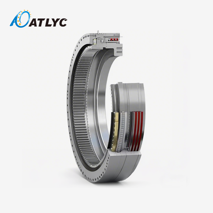
Slewing bearings employ single-row or double-row ball or roller elements in separate raceways. Their larger diameters and integrated gear teeth create different alignment concerns focused on gear mesh accuracy and mounting flange flatness. The alignment process emphasizes bolt circle concentricity rather than inner ring positioning.
Traditional deep groove ball bearings rely on elastic deformation within the balls to accommodate minor misalignment. Their point-contact geometry tolerates angular errors up to 0.3 degrees without significant performance penalties. This inherent flexibility contrasts sharply with crossed roller designs, where line contact demands stricter alignment control.
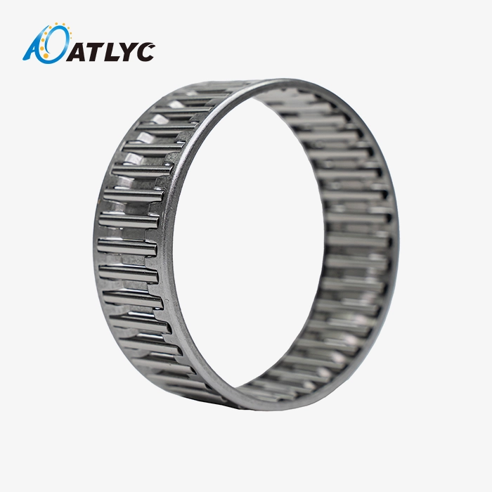
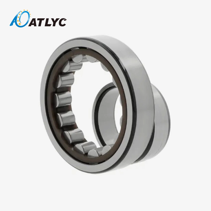
Cylindrical roller bearings with separate inner and outer rings require careful axial positioning but tolerate moderate angular misalignment. Their single-direction load capacity simplifies installation compared to crossed roller bearings handling multi-axis forces simultaneously.
The integral outer ring of RE series bearings provides exceptional rigidity for applications requiring precise outer housing rotation. This design choice influences alignment methodology—whereas bearings with split outer rings allow adjustment during installation, the solid outer ring of RE configurations demands that shaft-mounted inner rings achieve perfect alignment before outer ring installation.
Application-Specific Selection Guidance
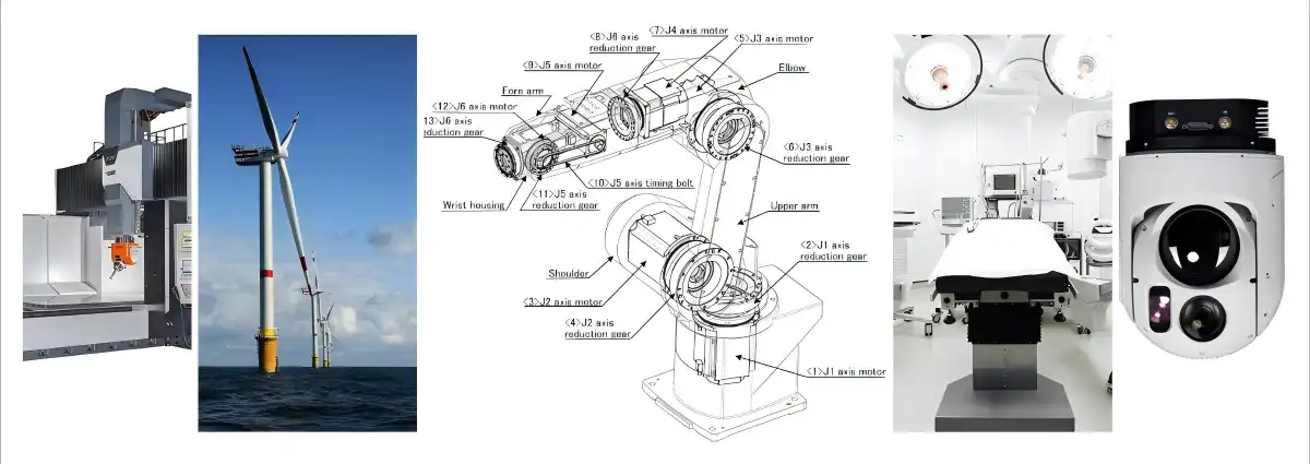
Robotic joint applications benefit from crossed roller bearing capabilities to handle combined loads within compact envelopes. The alignment precision directly affects robot positioning accuracy and path repeatability. Machine tool rotary tables similarly depend on exact alignment to maintain workpiece concentricity during multi-axis machining operations.
Medical imaging equipment rotates heavy detector assemblies with extreme smoothness requirements. Any vibration from bearing misalignment degrades image quality. Precision measuring instruments cannot tolerate the dimensional instability introduced by improperly aligned bearings, as measurement errors compound throughout kinematic chains.
IC manufacturing devices manipulating silicon wafers demand ultra-clean operation without particle generation. Misaligned bearings produce wear debris contaminating cleanroom environments. The operational stakes in these applications justify rigorous alignment procedures.
| Bearing Type | Alignment Tolerance | Installation Complexity | Multi-Axis Load Capacity | Typical Application |
|---|---|---|---|---|
| Cross Roller Bearing RE Series | ±0.003-0.008mm | High - requires precision tools | Excellent - radial, axial, moment | Robotic joints, rotary tables |
| Slewing Bearing | ±0.02-0.05mm | Moderate - focus on flange flatness | Excellent - with gear drive | Cranes, wind turbines |
| Deep Groove Ball Bearing | ±0.01-0.03mm | Low - self-aligning capability | Limited - primarily radial | Electric motors, pumps |
| Cylindrical Roller Bearing | ±0.005-0.015mm | Moderate - axial positioning critical | Moderate - radial only | Gearboxes, rolling mills |
Maintenance and Longevity: Ensuring Long-Term Proper Alignment
Initial installation alignment represents only the starting point. Operational factors continuously influence bearing geometry, requiring ongoing monitoring to sustain performance.
Routine Inspection Protocols
Establish vibration monitoring baselines during commissioning, measuring acceleration levels at bearing housings using tri-axial sensors. Frequency spectrum analysis reveals developing issues—subsynchronous peaks indicate looseness, while harmonics of running speed suggest wear progression. Monthly trending identifies gradual deterioration before catastrophic failure occurs.
Temperature monitoring provides complementary diagnostic data. Infrared thermography captures bearing housing temperatures during operation, with measurements 15-20°C above ambient considered normal for crossed roller bearings under moderate loads. Sudden temperature increases signal lubrication breakdown or internal damage requiring immediate investigation.
Acoustic emission testing detects microscopic crack propagation invisible to other methods. Ultrasonic sensors mounted near bearing housings capture high-frequency stress waves generated by material failure processes. This predictive technology enables condition-based maintenance scheduling rather than reactive repairs.
Material Wear Considerations
The Gcr15 and Gcr15SiMn bearing steels maintain hardness between 58-64 HRC, providing excellent wear resistance in the Cross roller bearing RE series. Over-extended service periods, rolling contact fatigue initiates subsurface cracks that eventually reach surface raceways as spalling. Proper alignment distributes contact stresses uniformly, maximizing the calculated L10 bearing life.
Contamination accelerates wear progression dramatically. Particles entering the bearing raceway act as abrasives, grinding away hardened surfaces. Effective sealing systems prevent ingress while retaining lubricant. Regular lubricant analysis identifies contamination sources before extensive damage occurs.
Corrosion represents another degradation mechanism, particularly in humid environments or where water contamination occurs. Rust formation on precision-ground surfaces creates roughness that disrupts smooth rotation and accelerates wear. Proper storage procedures and protective coatings safeguard bearings during idle periods.
Supplier Support and Warranty Considerations
Partnering with certified manufacturers holding ISO 9001 and IATF 16949 certifications ensures consistent quality backed by documented quality management systems. These certifications demonstrate commitment to continuous improvement and customer satisfaction through rigorous auditing processes.
Comprehensive technical support accelerates troubleshooting when operational issues arise. Experienced application engineers analyze failure modes, recommend corrective actions, and provide installation training. This expertise proves particularly valuable for complex crossed roller bearing installations requiring specialized knowledge.
Warranty coverage protecting against premature failure provides financial risk mitigation. Reputable suppliers stand behind their products with defined warranty periods tied to proper installation and maintenance practices. Documentation requirements typically include alignment verification records and routine inspection data, emphasizing the importance of systematic bearing management.
Procurement Insights: Selecting and Ordering the Right Cross Roller Bearing RE Series
Strategic procurement decisions extend beyond initial purchase price, encompassing total cost of ownership throughout equipment lifecycles. Informed buying practices balance cost considerations against quality, reliability, and supplier capabilities.
Lead Time and Delivery Logistics
Standard Cross roller bearing RE series configurations with common dimensions ship from stock within days, supporting rapid equipment repairs and minimizing downtime costs. Custom specifications requiring non-standard dimensions or modified accuracy grades extend lead times to 6-12 weeks, depending on manufacturing complexity.
Bulk ordering for OEM production runs benefits from volume discounts while ensuring consistent component quality across production batches. Establishing blanket purchase orders with scheduled releases synchronizes bearing deliveries with assembly line requirements, reducing inventory carrying costs while maintaining production flow.
International shipping considerations impact total procurement timelines. Sea freight from Asian manufacturing centers to North American destinations requires a 4-6 week transit time but offers significant cost advantages for large orders. Air freight accelerates delivery to 5-7 days when urgency justifies premium transportation costs.
Evaluating Supplier Credibility
Manufacturing capacity directly influences delivery reliability and quality consistency. Facilities operating multiple production lines demonstrate scalability to meet growing demand without compromising lead times. Site visits reveal production capabilities, quality control procedures, and technical expertise firsthand.
Engineering support distinguishes commodity suppliers from value-added partners. Application engineers providing bearing selection guidance, installation training, and failure analysis assistance reduce total ownership costs through optimized performance and extended service life. This technical collaboration proves particularly valuable when developing new equipment designs.
Certification credentials validate manufacturing quality systems. ISO 9001 certification demonstrates general quality management competency, while IATF 16949 specifically addresses automotive industry requirements, including advanced product quality planning and production part approval processes. These certifications require annual surveillance audits to maintain compliance rigor.
OEM Versus Aftermarket Considerations
Original equipment manufacturer bearings incorporate design refinements optimized for specific applications. Dimensional tolerances, material specifications, and quality grades match exact equipment requirements, ensuring drop-in compatibility and predictable performance.
Aftermarket alternatives offer cost savings ranging from 20-40% compared to OEM components. Quality varies significantly across suppliers—premium aftermarket manufacturers maintain equivalent specifications to OEM products, while budget alternatives compromise materials or accuracy grades. Careful specification verification prevents costly failures from substandard components.
The procurement strategy should align with application criticality. Mission-critical equipment justifies premium OEM components backed by comprehensive warranties and technical support. Non-critical applications with accessible maintenance access tolerate greater risk, making cost-effective aftermarket alternatives viable.
Embedding alignment guidance within procurement specifications ensures suppliers understand installation requirements. Purchase orders referencing specific alignment tolerances, measurement procedures, and acceptance criteria establish clear quality expectations. This proactive approach prevents disputes and ensures delivered bearings meet application demands.
Conclusion
When installing crossed roller bearings from the RE series, the performance, dependability, and operating life of the equipment depend on how well the inner rings are lined up. The split inner ring design calls for methodical assembly steps that stress checking dimensions, measuring accurately, and applying torque in a planned way. Understanding the most common reasons for misalignment, such as uneven mounting surfaces and temperature expansion effects, lets you take strategic steps to protect the integrity of the bearing.
The step-by-step alignment procedure described here is based on tried-and-true methods used in high-precision fields like robotics, machine tools, and medical equipment production. Regular maintenance checks like vibration analysis, temperature trending, and acoustic emission testing keep the alignment solid for the whole service life. Cost and supplier capabilities must be balanced in strategic procurement decisions to ensure reliable component sourcing that supports long-term operational success.
FAQ
1. What tools are essential for precise RE series inner ring alignment?
Achieving proper alignment requires dial indicators with magnetic bases for runout measurement, torque wrenches calibrated to ±4% accuracy for consistent fastener tightening, and precision feeler gauges verifying mounting surface perpendicularity. Laser alignment systems provide advanced capabilities for large-diameter installations where dial indicator reach becomes limiting. Surface roughness testers validate mounting surface finish meets bearing specifications. Digital micrometers measuring to 0.001mm resolution confirm shaft and bore dimensions fall within the specified tolerance bands.
2. How frequently should alignment inspections occur during operation?
Initial commissioning requires continuous monitoring during the break-in period—typically the first 100 operating hours. Vibration and temperature baselines established during this phase guide future comparisons. Quarterly inspections suit moderate-duty applications, while high-cycle or critical equipment demands monthly verification. Any operational changes, including load increases, speed modifications, or unusual noise, warrant immediate inspection regardless of scheduled intervals.
3. Can misalignment be corrected without complete bearing disassembly?
Minor misalignment sometimes responds to fastener torque adjustment without full disassembly. Loosening mounting bolts, repositioning components, and retightening following proper sequences corrects small errors. This approach succeeds only when misalignment stems from fastening issues rather than dimensional problems. Significant misalignment exceeding 0.02mm typically requires complete disassembly, root cause investigation, and corrective machining before reinstallation attempts.
Partner with ATLYC: Your Trusted Cross Roller Bearing RE Series Manufacturer
ATLYC brings fifteen years of bearing manufacturing excellence to your precision motion control challenges. Our ISO 9001 and IATF 16949 certified facilities produce Cross roller bearing RE series components meeting P2 through P6 accuracy grades, supporting applications from industrial robotics to medical imaging systems. With 120 dedicated professionals across production, quality assurance, and engineering departments, we deliver consistent quality backed by comprehensive technical support.
Our global customer base spanning South Korea, the United States, Germany, Russia, Iran, and Turkey trusts ATLYC for stable supply, competitive pricing, and expert application guidance. Whether you require standard configurations from our extensive inventory or custom-engineered solutions for specialized applications, our team provides alignment training, installation support, and ongoing maintenance consultation, ensuring optimal bearing performance.
Contact our engineering team at auto@lyautobearing.com to discuss your crossed roller bearing requirements. We provide detailed specifications, application analysis, and competitive quotations for Cross roller bearing RE series supplier partnerships supporting your equipment performance objectives and production timelines.
References
1. Harris, T.A. & Kotzalas, M.N. (2006). Advanced Concepts of Bearing Technology: Rolling Bearing Analysis. CRC Press, Boca Raton.
2. Palmgren, A. (1959). Ball and Roller Bearing Engineering. SKF Industries Inc., Philadelphia.
3. Eschmann, P., Hasbargen, L. & Weigand, K. (1985). Ball and Roller Bearings: Theory, Design and Application. John Wiley & Sons, Chichester.
4. ISO 492:2014. Rolling bearings — Radial bearings — Geometrical product specifications (GPS) and tolerance values. International Organization for Standardization, Geneva.
5. Kingsbury, E. (1985). "Cross Roller Bearing Technology for Precision Rotary Tables," Precision Engineering, Volume 7, Issue 3, pp. 129-137.
6. Weck, M. & Brecher, C. (2006). Werkzeugmaschinen 4: Automatisierung von Maschinen und Anlagen. Springer-Verlag, Berlin.
Learn about our latest products and discounts through SMS or email