- English
- French
- German
- Portuguese
- Spanish
- Russian
- Japanese
- Korean
- Arabic
- Greek
- German
- Turkish
- Italian
- Danish
- Romanian
- Indonesian
- Czech
- Afrikaans
- Swedish
- Polish
- Basque
- Catalan
- Esperanto
- Hindi
- Lao
- Albanian
- Amharic
- Armenian
- Azerbaijani
- Belarusian
- Bengali
- Bosnian
- Bulgarian
- Cebuano
- Chichewa
- Corsican
- Croatian
- Dutch
- Estonian
- Filipino
- Finnish
- Frisian
- Galician
- Georgian
- Gujarati
- Haitian
- Hausa
- Hawaiian
- Hebrew
- Hmong
- Hungarian
- Icelandic
- Igbo
- Javanese
- Kannada
- Kazakh
- Khmer
- Kurdish
- Kyrgyz
- Latin
- Latvian
- Lithuanian
- Luxembou..
- Macedonian
- Malagasy
- Malay
- Malayalam
- Maltese
- Maori
- Marathi
- Mongolian
- Burmese
- Nepali
- Norwegian
- Pashto
- Persian
- Punjabi
- Serbian
- Sesotho
- Sinhala
- Slovak
- Slovenian
- Somali
- Samoan
- Scots Gaelic
- Shona
- Sindhi
- Sundanese
- Swahili
- Tajik
- Tamil
- Telugu
- Thai
- Ukrainian
- Urdu
- Uzbek
- Vietnamese
- Welsh
- Xhosa
- Yiddish
- Yoruba
- Zulu
Cross roller bearing RE series: RE–REH–REV, Which Variant for You?
When you need precision bearings for important automation projects, the difference between the RE, REH, and REV types can have a big effect on how well and how long your machinery lasts. The Cross roller bearing RE series has three different structural configurations, and each one is best for a certain type of mounting and load. The normal RE version has an outer ring that is one piece and an inner ring that is split in half. This gives the outer ring very accurate spinning. REH adds fixing holes to the outer ring to make installation easier, and REV completely flips the structure, making the inner ring solid and the outer ring split. This is perfect when your application needs the inner ring to rotate with more precision. By knowing about these changes in structure, you can make sure that the bearings you use meet your specific operating needs.
Understanding the Cross Roller Bearing RE Series
Structural Design and Working Principle
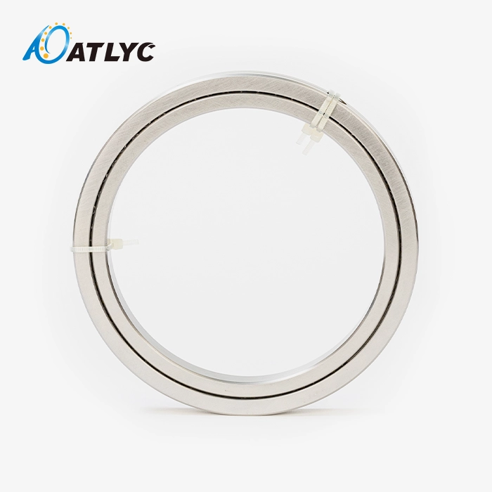
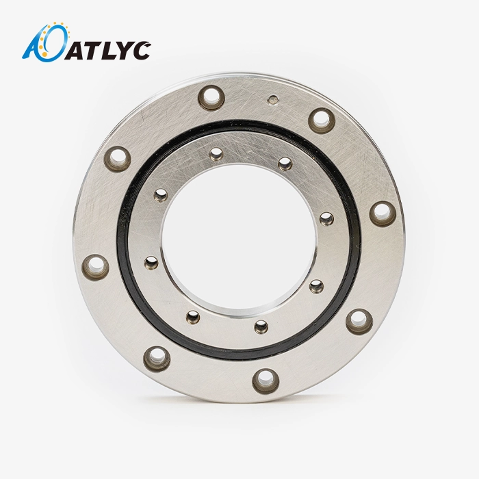
It is important to note that the Cross roller bearing RE series is a specific type of precision rolling bearing with its own unique structure. The normal RE version has an outer ring that is solid and merged, and an inner ring that is split into two different pieces. This design is the structure opposite of the RB series, and it has clear benefits for uses that need very accurate outer ring spinning.
Inside the bearing track, V-shaped rollers that are rectangular in shape are placed at right angles to each other every 90 degrees inside the raceway. This crossed design lets the bearing handle loads coming from multiple directions at the same time, which is a very important feature for complicated industrial uses. Roller spacers, also called cages, keep adjacent rollers from touching directly. This lowers the friction coefficient and makes the bearing last a lot longer than with regular designs.
The horizontal wheel design of the Cross roller bearing RE series is what makes the working concept work. It spreads loads evenly across many contact points. One set of rollers holds the load when radial forces are applied. The perpendicular roller set is moved by axial forces. Moment loads are handled by both sets of rollers working together, which gives the structure a very rigid feel in a very small space.
Technical Specifications and Dimensional Range
| Specification | Range/Value |
|---|---|
| Inner Diameter | 20-1100mm |
| Outer Diameter | 70-1500mm |
| Width | 12-110mm |
| Material | Gcr15, Gcr15SiMn |
| Precision Grades | P6, P0, P5, P4, P2 |
These specs show that crossed roller bearings can be used on a wide range of commercial scales. The wide range of sizes can fit a wide range of devices, from small medical instruments with 20mm inner diameters to huge industrial robots with 1100mm bore sizes. You can choose between Gcr15 and Gcr15SiMn as a material to get the best performance in a variety of working conditions. Gcr15SiMn has better hardenability for bigger cross-sections.
You can find a good balance between cost and accuracy with the precision grades, which range from P6 (standard) to P2 (ultra-precision). Applications that need sub-micron positioning accuracy, like IC manufacturing devices, usually ask for P4 or P2 grades. On the other hand, P5 or P0 grades are fine for general industrial automation equipment.
Performance Advantages in Demanding Environments
Having crossed rollers gives you a number of performance benefits that directly address common problems in designing precise machinery. Being able to handle radial, axial, and moment loads all at the same time in a single bearing means you don't need complicated bearing arrangements. This makes your assembly simpler and reduces the number of places where something could go wrong.
In traditional bearing systems, radial and thrust bearings are often kept separate, which takes up valuable mounting space and makes the assembly heavier. The thin-wall design of the RE series reduces the installation space needed by up to 40% compared to traditional bearing combinations. This lets machine designs be smaller without affecting the strength or load capacity of the structure.
The low-friction action comes from the perfectly spaced, orthogonal rollers. In practice, this means that your tools will run more smoothly, use less power (15–20% less than with comparable ball bearings), and last longer. When the outer case turns, like in rotating tables and swivel joints, the excellent runout accuracy that comes with the continuous outer ring design ensures that the bearing always works well.
Comparing RE, REH, and REV Variants: Which One Fits Your Needs?
RE Variant: Standard Configuration for Outer Ring Rotation
When the outer ring of the cross roller bearing RE series needs to rotate for your application, the standard RE variant works best. The entire outer ring is very strong and runs accurately, so there are no more of the usual precise problems that come with split outer ring designs. The split inner ring makes installation easier and lets maintenance workers get to the part without taking apart all the other machinery around it.
Robotic arm joints where the outer body turns, rotating tables on machine centers, and precision tracking tools are some of the uses that gain the most from the RE design. In factories that use robotic automation to put together automotive parts, specifying RE variants over other bearing types has been shown to improve positioning repeatability by ±2 arc-seconds.
As well as better mounting surface contact, the solid outer ring design spreads installation pressures more widely and lowers the risk of bearing distortion during assembly. This feature is especially useful for applications with a diameter greater than 500 mm, since mounting distortion can make operation much less accurate.
REH Variant: Enhanced Mounting Capability
For the REH version, the outer ring has fixing holes placed in a way that makes fitting easier and cuts down on setup time. This change fixes a problem that maintenance teams often have: it's hard to place and secure large-diameter precision bearings in equipment layouts that aren't very open.
Field data from makers of industrial machinery shows that installing REH types takes about 30% less time than installing standard RE bearings, which need separate mounting mounts or complicated tightening arrangements. The mounting holes that have already been drilled can accept standard fasteners. This means that no custom fabrication is needed, and the initial installation and replacement processes can be done faster during routine maintenance.
In addition to being easier to install, the REH configuration keeps all of the performance features of the standard RE variant. Load limits, rotary accuracy, and friction factors stay the same, so you don't have to give up performance to make fitting easier. Because of this, REH is the best choice for situations where bearings need to be replaced often or where installation access is limited.
REV Variant: Reversed Structure for Inner Ring Rotation
The structure is completely turned around in the REV version, which has a solid inner ring and a split outer ring. This improvement to the design is for uses where the inner ring needs to spin precisely and quickly. The built-in inner ring gives the inner ring rotation the same rigidity and accuracy benefits as the standard RE for the outer ring rotation.
Precision rotary tables where the table surface links to the inner ring, measuring tools that need very accurate inner ring runout, and specialised factory equipment for making semiconductors are all common uses for REV versions. The split outer ring makes it easier to design the housing and replace the bearings without taking the whole thing apart.
Performance tests on machining center rotary tables with REV variants showed that radial runout values were always less than 3 microns across all dimensions, meeting the high standards for accuracy needed for five-axis machining operations. The backwards structure also makes it easier to apply lubricant in situations where the inner ring turns all the time. This increases the time between repair visits and lowers the cost of running the machine.
Comparative Performance Analysis
| Feature | RE Variant | REH Variant | REV Variant |
|---|---|---|---|
| Outer Ring | Integral (solid) | Integral with holes | Split (two-piece) |
| Inner Ring | Split (two-piece) | Split (two-piece) | Integral (solid) |
| Optimal for | Outer ring rotation | Simplified mounting | Inner ring rotation |
| Installation | Standard mounting | Bolt-hole mounting | Housing integration |
| Typical Applications | Robot joints, rotary tables | High-frequency replacement | Precision indexing, measuring |
Understanding these structural differences enables you to align bearing selection with your specific operational conditions. The decision should factor in which ring rotates in your application, accessibility for maintenance procedures, and the precision requirements for the rotating element.
How to Choose the Right Cross Roller Bearing RE Series for Your Procurement Goals
Assessing Load Requirements and Operating Conditions
To choose the right bearings, you need to do an accurate load study. First, figure out how much radial, axial, and moment stress your application can handle when it is working normally and when it is under the most stress. The crossed roller design works well with combined loads, but you need to make sure that the bearing size and type you choose have enough safety factors, which are usually 1.5 for normal use and 2.5 for shock-load situations.
Operating speed has a big effect on the choice of bearing. Crossed roller bearings are great for precise tasks, but they usually work at slower speeds than deep groove ball bearings. Applications that need constant spinning speeds higher than 500 RPM should pay extra attention to how they lubricate and get rid of heat. Talk to the bearing makers about the fastest speeds that are possible for your size and precision grade.
Extreme temperatures, contamination exposure, and humidity levels are some of the environmental factors that affect the choice of bearing material and seal configurations. The standard Gcr15 material works well in temperatures from -20°C to 120°C. For uses outside of these areas, you need special materials or extra cooling or heating features.
Precision Grade Selection and Cost Considerations
The choice of precision grade has a direct effect on both the cost of the bearings and how well the machine works. Moving from P6 to P2 grades means that manufacturing tolerances get tighter over time. P2 bearings are more expensive than P0 peers, often three to four times as much. Instead of defaulting to the highest precision, this choice should be based on how accurate your application really needs to be.
P5 or P0 precision grades usually work well for general industrial automation equipment that needs to be able to place itself within ±10 microns. P4 or P2 specifications are appropriate for measuring tools, equipment used to make semiconductors, and ultra-precision machining tasks. If you do a cost-benefit study that takes into account higher return rates and less waste, you can show that better accuracy grades are worth the extra money in the right situations.
The budget should include more than just the original buy price. It should also include the total cost of ownership. Higher precision bearings usually have longer service lives, less maintenance, and use less energy. These benefits can make up for their higher initial costs over a 5–10 year operational period.
Supplier Evaluation and Quality Assurance
Choosing a trustworthy bearing maker or provider is an important purchase choice that goes beyond comparing prices. Manufacturers with ISO 9001 and IATF 16949 certifications have quality management systems that are well-established and meet international standards for the car and industry sectors. With these certifications, you can be sure that the manufacturing process includes methods for systematic quality control and continuous improvement.
When making long-term supply partnerships, it's important to think carefully about production capacity and scalability. Suppliers with a wide range of products and various production sites can better handle changes in your order volume and help you add new products to your line. Ask for detailed details about the bearing types you need, such as production wait times, minimum order amounts, and stocking policies.
Superior suppliers are different from commodity vendors because they can offer technical support. Help with engineering during the specification phase, the ability to customise for OEM uses, and quick support after the sale all play a big role in how well a bearing is put into use. Suppliers that offer application engineering consultations can help you choose the best bearings and find ways to save money on costs by making changes to the design.
Installation and Maintenance Guide for the RE Series Cross Roller Bearings
Preparation and Installation Best Practices
Proper installation procedures directly influence bearing performance and service life. Before beginning installation, verify that mounting surfaces meet flatness and perpendicularity tolerances specified in the bearing documentation—typically within 0.02mm for precision applications. Surface roughness should not exceed Ra 1.6 on mounting faces to ensure uniform load distribution and prevent localized stress concentrations.
Clean all components thoroughly using appropriate solvents to remove preservation coatings and any contamination. Even microscopic particles can compromise bearing performance, so maintain clean-room protocols when handling precision-grade bearings. Inspect the bearing for any transportation damage, paying particular attention to raceway surfaces and roller condition.
During installation of the Cross roller bearing RE series, apply uniform torque when tightening mounting bolts, following a cross-pattern sequence to prevent bearing distortion. Use a calibrated torque wrench and adhere to manufacturer-specified torque values—over-tightening causes preload issues and accelerated wear, while under-tightening permits movement that damages mounting surfaces. Verify bearing rotational smoothness after mounting but before connecting to driven equipment.
Routine Maintenance and Troubleshooting Strategies
Establishing a preventive maintenance schedule significantly extends bearing service life and prevents unexpected downtime. Lubrication represents the most critical maintenance activity for crossed roller bearings. Applications operating continuously should receive lubrication replenishment every 2000-3000 operating hours, though specific intervals depend on load conditions, speed, and environmental factors.
Monitor bearing temperature during normal operation to establish baseline values. Temperature increases of 10-15°C above baseline indicate potential lubrication degradation, contamination ingress, or preload issues requiring investigation. Vibration analysis using accelerometers can detect early-stage bearing damage before performance degradation becomes apparent, allowing planned maintenance rather than emergency repairs.
Common troubleshooting scenarios include excessive noise, increased friction or torque, and temperature elevation. Noise typically indicates inadequate lubrication or contamination, requiring immediate attention to prevent accelerated wear. Increased friction suggests preload deviation or lubricant breakdown. Temperature elevation often stems from over-tightening, misalignment, or excessive load conditions. Addressing these issues promptly prevents minor problems from escalating into bearing failure and associated equipment damage.
Extending Operational Life Through Proactive Strategies
Several proactive strategies maximize bearing longevity and return on investment. Implementing proper sealing systems prevents contamination ingress—the leading cause of premature bearing failure in industrial environments. Labyrinth seals, contact seals, or shield configurations should match your operating environment's contamination level and accessibility for maintenance.
Maintain optimal operating temperature through adequate ventilation or cooling provisions. Bearing life decreases exponentially with temperature elevation above recommended ranges—every 10°C increase above 70°C can reduce bearing life by approximately 50%. Applications generating significant heat should incorporate thermal management into the machine design phase.
Document bearing installation dates, maintenance activities, and performance observations to establish reliable service life data for your specific application conditions. This historical data enables optimized maintenance scheduling and informs future bearing procurement decisions, particularly when evaluating cost-performance tradeoffs between precision grades or variant selections.

Conclusion
Selecting between RE, REH, and REV variants requires careful consideration of your application's rotational requirements, mounting constraints, and precision specifications. The standard RE variant optimizes outer ring rotation accuracy, REH adds installation convenience through integrated mounting holes, and REV delivers superior inner ring rotational precision through its reversed structure. Understanding these fundamental differences, combined with thorough load analysis and supplier evaluation, positions your procurement decisions for long-term success. The crossed roller bearing technology continues advancing precision automation capabilities across automotive manufacturing, industrial robotics, and measurement instrumentation—making informed variant selection increasingly important as machinery accuracy demands escalate in competitive global markets.
FAQ
1. What load capacities do crossed roller bearings provide compared to ball bearings?
Crossed roller bearings deliver significantly higher load capacity in all directions compared to equivalently sized ball bearings. The cylindrical roller contact provides greater load-carrying area than point contact in ball bearings, typically offering 2-3 times higher radial capacity and 3-5 times higher axial capacity within the same envelope dimensions.
2. How do RE series bearings compare with slewing bearings for rotary applications?
RE series bearings excel in compact precision applications requiring high accuracy and moderate loads, while slewing bearings suit large-diameter, heavy-load applications where space constraints are less critical. Slewing bearings typically accommodate larger moment loads but operate at lower rotational accuracy levels than precision-grade crossed roller bearings.
3. Can you customize RE series bearings for OEM applications?
Reputable manufacturers offer customization options, including modified mounting configurations, special sealing arrangements, precision grade selection, and dimensional modifications within manufacturing capabilities. Customization typically requires minimum order quantities and extended lead times, making it most suitable for series production rather than prototype quantities.
What factors determine bearing replacement intervals?
Replacement intervals depend on operating conditions, including load magnitude, speed, temperature, lubrication quality, and environmental contamination. Properly maintained bearings in moderate operating conditions typically achieve 20,000-30,000 operating hours. Monitoring programs tracking temperature, vibration, and noise enable condition-based replacement strategies that optimize bearing utilization while preventing unexpected failures.
Partner with ATLYC: Your Trusted Cross Roller Bearing RE Series Supplier
Selecting the right precision bearing variant represents just the beginning of successful procurement—partnering with a manufacturer that delivers consistent quality, reliable lead times, and comprehensive technical support ensures long-term operational success. ATLYC brings 15 years of specialized bearing manufacturing experience to your precision machinery projects, backed by ISO 9001 and IATF 16949 certifications that demonstrate our commitment to international quality standards.
Our engineering team supports your specification process with application consultations, customization capabilities for OEM requirements, and technical documentation that simplifies integration. We maintain production capacity across six specialized workshops with 120 skilled professionals, enabling competitive pricing without compromising the precision and reliability your applications demand. Our global shipping network serves automotive and industrial equipment manufacturers throughout the United States, Germany, and beyond with transparent lead times and flexible order quantities.
Contact our technical sales team at auto@lyautobearing.com to discuss your crossed roller bearing requirements. We'll provide detailed specifications, competitive quotations, and engineering support to ensure optimal bearing selection for your specific application. Discover why leading OEMs and distributors trust ATLYC as their preferred Cross roller bearing RE series manufacturer for mission-critical precision applications.
References
1. Harris, T.A. & Kotzalas, M.N. (2006). Advanced Concepts of Bearing Technology: Rolling Bearing Analysis, Fifth Edition. CRC Press, Taylor & Francis Group.
2. ISO 199:2014. Rolling bearings — Thrust bearings — Geometrical product specifications (GPS) and tolerance values. International Organization for Standardization.
3. Weck, M. & Brecher, C. (2006). Werkzeugmaschinen Fertigungssysteme: Konstruktion, Berechnung und messtechnische Beurteilung, Volume 2. Springer-Verlag Berlin Heidelberg.
4. SKF Group. (2018). Rolling Bearings Catalogue: Design and application engineering data for the selection and application of rolling bearings. SKF Group Technical Publication.
5. Schaeffler Technologies AG & Co. (2019). Crossed Roller Bearings and Cylindrical Roller Bearings: Technical Design and Application Guidelines. Schaeffler Technical Publications.
6. American National Standards Institute. (2015). ANSI/ABMA Standard 12.1: Instrument Ball Bearings – Metric Design. American Bearing Manufacturers Association.
Learn about our latest products and discounts through SMS or email