- English
- French
- German
- Portuguese
- Spanish
- Russian
- Japanese
- Korean
- Arabic
- Greek
- German
- Turkish
- Italian
- Danish
- Romanian
- Indonesian
- Czech
- Afrikaans
- Swedish
- Polish
- Basque
- Catalan
- Esperanto
- Hindi
- Lao
- Albanian
- Amharic
- Armenian
- Azerbaijani
- Belarusian
- Bengali
- Bosnian
- Bulgarian
- Cebuano
- Chichewa
- Corsican
- Croatian
- Dutch
- Estonian
- Filipino
- Finnish
- Frisian
- Galician
- Georgian
- Gujarati
- Haitian
- Hausa
- Hawaiian
- Hebrew
- Hmong
- Hungarian
- Icelandic
- Igbo
- Javanese
- Kannada
- Kazakh
- Khmer
- Kurdish
- Kyrgyz
- Latin
- Latvian
- Lithuanian
- Luxembou..
- Macedonian
- Malagasy
- Malay
- Malayalam
- Maltese
- Maori
- Marathi
- Mongolian
- Burmese
- Nepali
- Norwegian
- Pashto
- Persian
- Punjabi
- Serbian
- Sesotho
- Sinhala
- Slovak
- Slovenian
- Somali
- Samoan
- Scots Gaelic
- Shona
- Sindhi
- Sundanese
- Swahili
- Tajik
- Tamil
- Telugu
- Thai
- Ukrainian
- Urdu
- Uzbek
- Vietnamese
- Welsh
- Xhosa
- Yiddish
- Yoruba
- Zulu
Where Are Pitch Bearings Used in Modern Wind Turbines?
Pitch bearings are at the base of each blade on a modern horizontal-axis wind turbine. They are between the blade and the rotor hub. Pitch bearing, which enables each blade to rotate around its long axis, allows the control system to set the blade angle to collect wind energy, limit loads, and feather the blade in bad weather. They are used on machines with geared drives, direct drives, that are on land or at sea, where the blade angle needs to change with the wind. OEM engineers, buyers, and distributors who want to know how these parts are made, where they work, and how to choose them should read this guide.

What Is a Pitch Bearing in a Wind Turbine?
Where the Bearing Sits
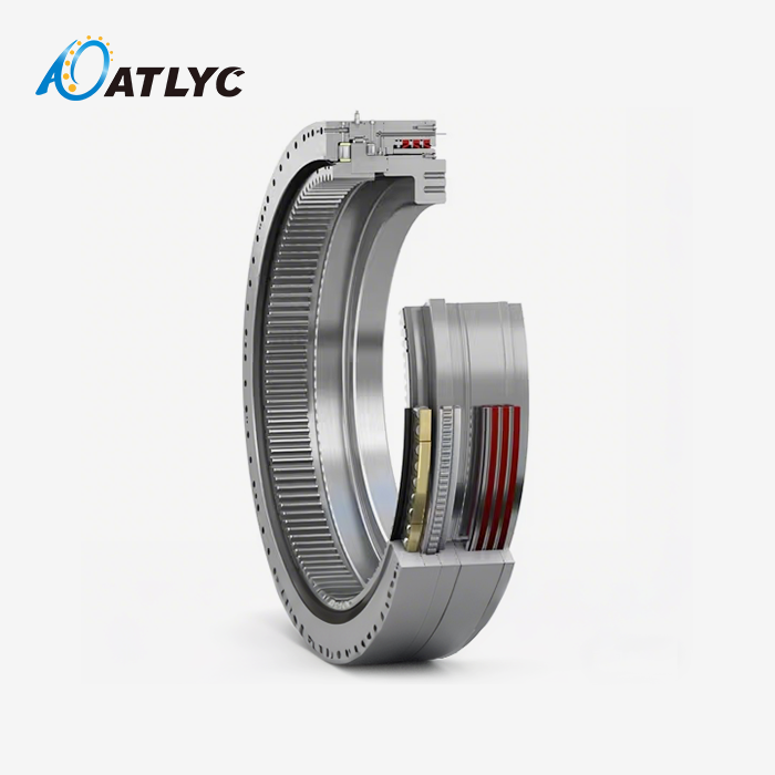
Pitch bearings in wind turbines are big rings that move back and forth and connect the hub of the rotor to the base of each blade. In order for a utility-scale turbine to work, each of its three blades needs its own bearing. The blade and the hub are joined by two rings. The blade can now turn around its long axis while the hub stays put. Most of the time, the pitch angle is between -5° and 90°. The blade can cut through the wind and slow down the rotor when it is at 90°. To do this, you call it feathering. When there is a grid fault, high winds, or too much speed, the controller can handle it because each blade moves on its own.
How It Differs From Neighboring Components
People often mistake the Pitch bearing for other parts in the hub and nacelle. The rotor shaft stays in place and turns thanks to the main shaft bearing. It's at the very top of the tower and faces the wind with the whole nacelle. The blade-root attachment is the nut and bolt joint between the blade and the bearing. That part of the machine that turns the bearing with a pinion is called the pitch drive. The Pitch bearing moves back and forth quickly and carefully when it does its job. It doesn't turn all the time. When duty goes back and forth, it causes lubrication and wear issues that are different from those that happen with bearings that are always turning.
Parts That Work Together
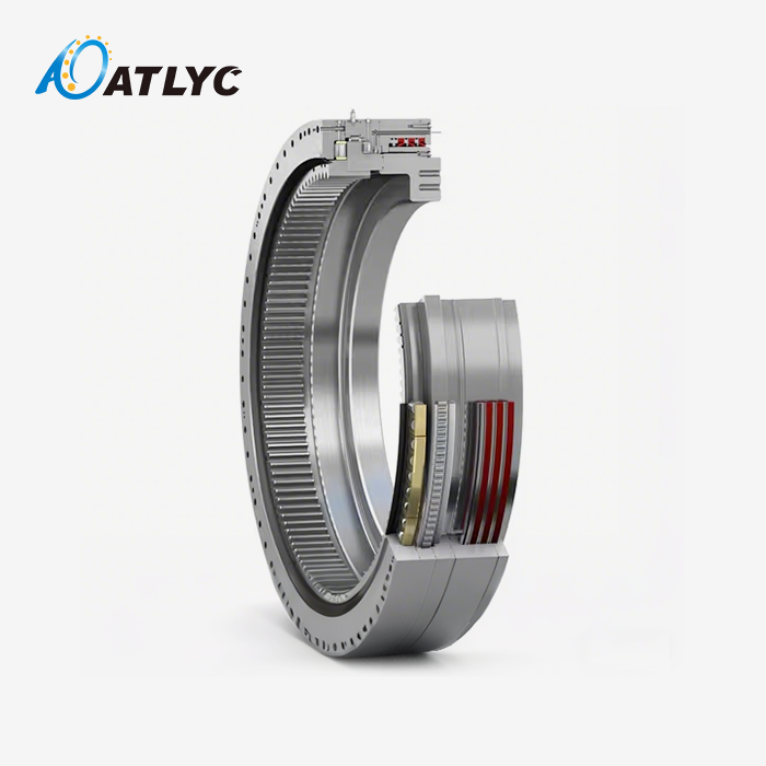
Cast raceways are held in place by the bearing's outside and inside rings, and rolling elements move between them. Water and grease can't get in because of seals. A lot of designs have a gear ring built in that fits with the pitch drive pinion. This gear ring can be in the design or not. Sensing and moving parts close the control loop. A sensor tells the motor where the blades are, and the motor moves them into place. These parts work together to move axial, radial, and overturning loads from the blade to the hub. They also make it possible to change the angle very precisely. If one part wears out, it can lead to backlash, higher motor current, or blades that aren't placed as accurately.
Where Pitch Bearings Are Used Across Wind Turbine Platforms
Horizontal-Axis Turbines, Geared and Direct Drive
Pitch bearings are primarily used in horizontal-axis wind turbines, which make up the majority of utility-scale projects. They can be found in machines with geared drives or direct drives. A gearbox in a geared-drive machine speeds up the generator's rotor. The generator is directly linked to the rotor in direct-drive machines. The drivetrain changes how the nacelle is laid out, but there still needs to be a pitch joint at the hub of each blade. Most turbines that change speeds depend on them. It holds the angle of the blades so that they collect energy when the wind speed is less than the rated speed. When the speed goes over what it can handle, the angle changes to keep the power steady. This is the next most important thing to know, after the rotor diameter, blade mass, rated power, pitch frequency, and OEM hub interface.
Onshore, Offshore, and Cold-Climate Sites
What the site's shape should be like. The table shows how well the most common platforms do.
| Platform | Main priority for the Pitch bearing | Reason |
|---|---|---|
| Onshore utility-scale (about 2–5 MW) | Cost, serviceability, contamination resistance | Frequent micro-adjustments and high-cycle vibration |
| Offshore (about 6–15 MW and above) | Corrosion protection, sealing, long service intervals | Salt spray, humidity, costly access |
| Cold-climate projects | Low-temperature steel and grease | Operation down to -40°C stresses raceways and seals |
| Smaller turbines | Compact size and cost | Lower blade loads call for smaller bearings |
Fixed-bottom and floating offshore wind farms both need to pass tough tests to make sure they are safe. The load picture moves around with the help of floating platforms.
Why Pitch Bearings Affect Turbine Performance
The bearing changes how well, safely, and quickly something can be found. The blades' weight, turbulence, axial and radial forces, and the shock of emergency braking are just some of the things that it has to deal with. If you move the blade the right way, it stays at the right angle of attack. This helps you control the rotor's speed and collect energy. It's harder to control, and the motor has to work harder when there is too much clearance, friction, wear, or gear backlash. Also, failure costs a lot. Most of the time, you need to book a crane and take off a blade to change a Pitch bearing. This leads to a lot of downtime and extra damage, especially when the work is done in another country.
Pitch Bearing Design and ATLYC Product Features
Structure and Size Range
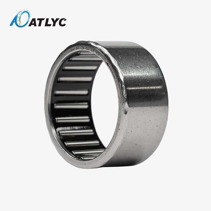
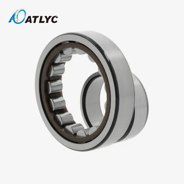
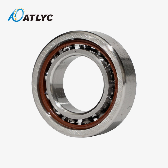
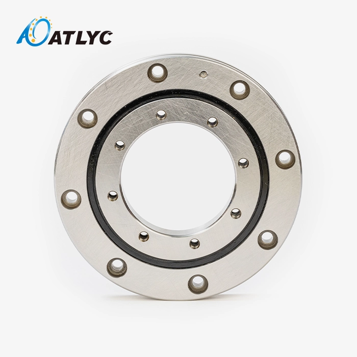
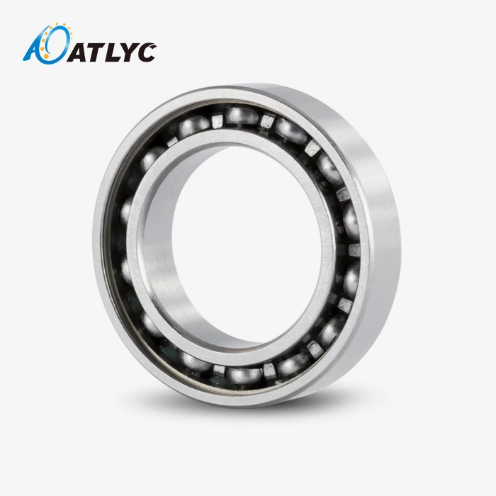
There are two main types of structures: full complement cylindrical roller bearings and double-row four-point contact ball bearings. Both blades have to carry heavy loads because they start and stop so often. For moderate loads, ball designs are the best balance between cost and moment capacity. Roller designs, on the other hand, make things stiffer. Sources in the business say that triple-row roller designs are often used on turbines with 10 MW or more. The outer diameter of an ATLYC Pitch bearing is usually between 1000 mm and 2500 mm, which is smaller than a yaw bearing and fits the space between the blade and root. The size of megawatt-class turbines with big blades changes based on how much load needs to be carried.
Heat Treatment, Gear Ring, Lubrication, and Sealing
The raceway is made harder all over by non-soft zone quenching at ATLYC. This gets rid of any soft spots that could wear out quickly when loads move back and forth. The blade angle can be changed more accurately because of a gear ring that is built in. Grease is spread across the raceway when it moves a lot because of how it's made. This is important since short oscillations make it hard for fresh grease to reach the area where the two parts touch. Many seals work together to keep water and dirt out, which is very helpful in places with a lot of humidity and salt spray.
Core Advantages for Wind Power Buyers
Here are some of the best features of this Pitch Bearing Line:
Operational precision: Carefully designed raceway contact reduces angle errors in blade positioning. Controller commands then turn into accurate blade movement, which supports steady power output as wind conditions shift across a day or a season.
Fatigue resistance: Careful material selection and controlled heat treatment give strong resistance to fatigue. Your equipment faces a lower chance of failure during frequent start-stop cycles and alternating load conditions over many years of service.
Lower upkeep needs: The sealing and lubrication design extends service intervals. This benefit matters most for offshore turbines, where maintenance access stays difficult and expensive, and every visit takes planning, vessels, and weather windows.
Incorrect positioning, damage from early wear and tear, and expensive service visits are three problems that buyers often bring up. These benefits solve all three of them.
How to Choose, Maintain, and Troubleshoot a Pitch Bearing
Selection Checklist
To choose a Pitch bearing, it's not enough to just look at the outside diameter or the price. For starters, you need to choose the shape, weight, diameter, pitch system, wind speed, temperature range, pitch frequency, and service life goal of the turbine. Then look at all the different kinds of loads, like radial and axial forces, tilting moments, reversing loads, shocks, and fatigue cycles. Check out the bearing's diameter, height, number of teeth, gear module, and clearance of the bolt holes. Check to see if the emergency feathering system, pitch motor, pinion, and encoder all work well with each other. In order to figure out ISO 281 life, keep in mind that the rotation should never stop. Because of this, ways of oscillating duty that are used in the NREL DG03 guideline need to be changed.
Lubrication, Installation, and Maintenance
It's hard to grease things that are moving slowly and back and forth. Always choose grease based on its temperature range, water resistance, ability to work under pressure, type of thickener, and ability to work with different seals. Don't mix things that don't go well with each other. Clean the flange, make sure it's flat, and make sure it's facing the right way. Carefully tighten the bolts. Check the backlash of the gears. Finally, run a functional test. Check the automatic lubrication system while the machine is in use and look for iron particles in the used grease. If necessary, tighten the mounting bolts again. Check the temperature, the motor current, the noise, and the state of the seals. For offshore replacements, you need to plan ahead for cranes, ships, and short periods of downtime.
Common Failure Causes and Troubleshooting
Problems with the gear mesh, not enough oil, dirt, corrosion, false brinelling, overloading, misalignment, broken seals, bad installation, or not enough oil are the main reasons why things break. Sometimes, tiny vibrations stop the lubricant film from filling up the contact again. This is known as false brinelling. You should look at operating data and trends to see if the noises you hear are normal or if the pitch motor current is going up. As part of condition-based maintenance, inspections, tracking of vibrations, data on torque, and analysis of lubricant are all done. With this method, problems are found early. If the gear tooth or raceway is badly broken, it usually can't be fixed to the tower and needs to be replaced.
Pitch Bearing Procurement and Supplier Selection for Global Buyers
Defining Your Need and Writing the RFQ
First, decide if you need something from a catalog, a direct replacement, an OEM-equivalent bearing, or a custom design. The original part number, drawings, interface dimensions, gear specifications, load range, operating temperature, lubrication needs, quantity, where the item is going, and certification requirements should all be in a good RFQ. Don't just look at the unit price when you compare quotes. You should also think about the warranty, the risk of downtime, the lead time, the inspection scope, the packaging, and the service life. Buyers usually also want ultrasonic testing of ring forgings, magnetic particle inspection of raceways and gear teeth, hardness depth checks, and tests for starting friction torque.
Pitch Bearing vs. Other Bearing Types
They're not the same, even though they look alike.
| Bearing type | Location | Motion | Key trait |
|---|---|---|---|
| Pitch bearing | Blade-to-hub joint | Small, oscillating angles | Large diameter, gear ring, heavy overturning moments |
| Yaw bearing | Nacelle-to-tower joint | Slow nacelle rotation | Larger than a pitch bearing |
| Conventional roller bearing | Shafts and housings | Continuous rotation | Not built for large diameter or integrated gearing |
Look at how it handles motion, load, gear arrangement, sealing, clearance, and fatigue before you choose a type.
What ATLYC Brings to a Pitch Bearing Program
Luoyang Auto Bearing Co., Ltd. is the name of the company that makes ATLYC. The first one opened in 2010 with just one fully automated deep groove ball bearing workshop. There are now six workshops with 120 skilled workers doing things like making things, doing research and development, checking the quality, and putting things together. The company has clients in South Korea, the US, Germany, Russia, Iran, and Turkey. It also works with ISO 9001 and IATF 16949. Exporting in the past has been good for the U.S. The OEMs and distributors plan ahead for long-term supplies and make sure the quality stays high.

Conclusion
Pitch bearings connect each blade to the rotor hub. The control system can change the angle of the blades for power management, emergency feathering, and regulating the load. Onshore and offshore turbines with geared drives and direct drives both use them. In offshore and cold climate sites, sealing and protecting against corrosion are the most important things to do. They can tilt, oscillate, and move with gears, which makes them different from yaw and general roller bearings. There should be an integrated gear ring, a double-row four-point contact ball or full complement cylindrical roller structure, good lubrication and sealing, and four points of contact between the balls or rollers in a good design. This is not the right way to choose based on diameter or price alone. You should also think about the full load range, interface dimensions, and service conditions. You can tell how long a bearing will last by how it is installed, oiled, and checked for damage.
FAQ
How many pitch bearings does a wind turbine have?
A machine with three blades usually has three because each blade has one. They are all in the middle of a blade root and a hub.
Are pitch bearings used offshore as well as onshore?
Yes. At offshore units, maintenance is hard to get to and costs a lot. That's why they need better sealing and corrosion protection.
What causes most pitch bearing failures?
A lot of the time, it's because of things like contamination, corrosion, misalignment, gear wear, and not lubricating well enough.
What does service life depend on?
How long a bearing lasts isn't just based on its diameter; it's also affected by the loads it's used under and how well it's maintained.
What information do I need to select a replacement?
Find out the original part number, drawings, interface dimensions, gear specifications, load data, operating temperature, amount of oil that needs to be used, and the climate where the gears will be used.
Request a Pitch Bearing Recommendation or Quotation
Please email auto@lyautobearing.com with your drawings, part numbers, load data, quantities, and delivery needs. Our techs will go over them with you. We are certified by ISO 9001 and IATF 16949 and have six workshops with 120 skilled workers. We make Pitch bearings. When you need OEM-equivalent replacements or help with a custom project, we can help. Go to https://aotezhoucheng.aixdb.cn/ and ask for a suggestion, a quote, or an engineering review to find out more.
References
1. IEC 61400-1: Wind Energy Generation Systems – Part 1: Design Requirements, 2019
2. ISO 281: Rolling Bearings – Dynamic Load Ratings and Rating Life, 2007
3. NREL, Wind Turbine Design Guideline DG03: Yaw and Pitch Rolling Bearing Life, 2009
4. Wind Energy Handbook (Burton, Jenkins, Sharpe, Bossanyi), 2011
5. ISO 12944-2: Paints and Varnishes – Corrosion Protection of Steel Structures by Protective Paint Systems – Classification of Environments, 2017
6. Wind Turbines: Fundamentals, Technologies, Application, Economics (Erich Hau), 2013
Learn about our latest products and discounts through SMS or email